HEXRCHardware Manual Installation and Configuration
2.4.4. Opto-Isolated Inputs
The digital inputs are opto-isolated and may be connected to current sourcing or current sinking devices, as
shown in Figure 2-25 and Figure 2-26. These inputs are designed to connect to other ground-referenced
circuits and are not intended for high-voltage isolation.
The opto-isolator's common connections can be directly connected to the drive's power supply; however,
doing so will effectively defeat the isolation and will reduce noise immunity.
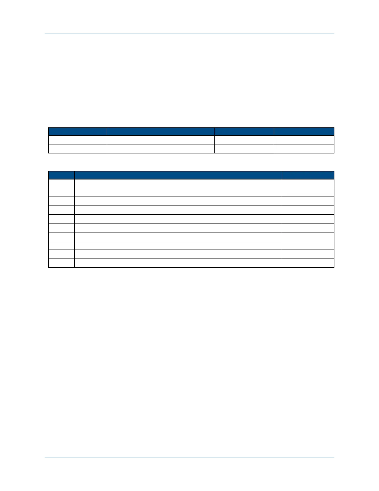
Table 2-20: Digital Input Specifications
Input Voltage Approximate Input Current Turn On Time Turn Off Time
+5 V 1 mA 200 usec 2000 usec
+24 V 6 mA 4 usec 1500 usec
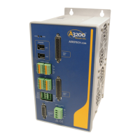
Table 2-21: Opto-Isolated Input Connector Pin Assignment
Pin# Description In/Out/Bi
4 Input Common for Opto-Inputs 0 - 3 Input
5 Optically-Isolated Input 0 Input
6 Optically-Isolated Input 1 Input
7 Optically-Isolated Input 2 Input
8 Optically-Isolated Input 3 Input
16 Input Common for Opto-Inputs 4 - 7 Input
17 Optically-Isolated Input 4 Input
18 Optically-Isolated Input 5 Input
19 Optically-Isolated Input 6 Input
20 Optically-Isolated Input 7 Input
36 Chapter 2 www.aerotech.com