HEXRCHardware Manual Installation and Configuration
2.3.1.2. Analog Encoder Interface
The HEXRC controller contains Ndrive MP10 drives with the MXU option. The drive is software-configured
to accept analog encoder signals (refer to the A3200Help file for information on the PositionFeedbackType
and EncoderMultiplicationFactor parameters). The encoder interpolation factor is software-selectable (refer
to the A3200Help file).
Table 2-8: Analog Encoder Specifications
Specification
Value
Input Frequency (max) 200 kHz
Input Amplitude 0.6 to 2.25 Vpk-Vpk
Interpolation Factor (software
selectable)
4,096
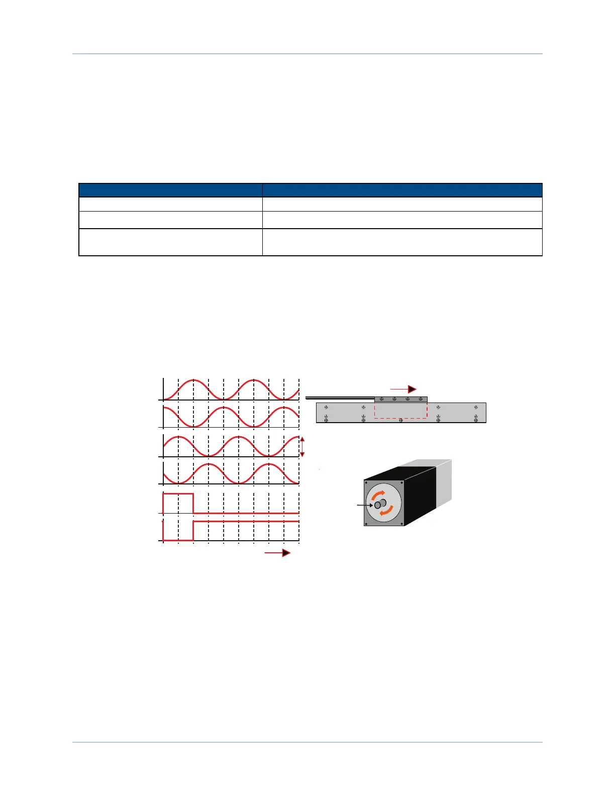
Refer to Figure 2-4 for the MXU typical input circuitry.
The encoder interface pin assignment is indicated in Section 2.3.1.
The gain, offset, and phase balance of the analog Sine and Cosine encoder input signals can all be adjusted
via controller parameters. Encoder signals should be adjusted using the Feedback Tuning tab of the Digital
Scope, which will automatically adjust the encoder parameters for optimum performance. See the
A3200Help file for more information.
Forcer Wires
SIN
SIN-N
COS
COS-N
MRK
MRK-N
Forcer
Magnet
Track
Motor Mounting
Flange (Front View)
Motor Shaft
CW Rotation
(Positive Direction)
LINEAR MOTOR
ROTARY MOTOR
Positive MOVE (Clockwise)
Positive MOVE
(Clockwise)
0° 90° 180° 270° 360° 450° 540° 630° 720° 810°
0° 90° 180° 270° 360° 450° 540° 630° 720° 810°
0° 90° 180° 270° 360° 450° 540° 630° 720° 810°
1V
pk-pk
Figure 2-4: Analog Encoder Phasing Reference Diagram
18 Chapter 2 www.aerotech.com