HEXRCHardware Manual Installation and Configuration
2.2. Electrical Installation
N O T E : The machine integrator, OEM, or end user is responsible for meeting the final protective ground-
ing requirements of the system.
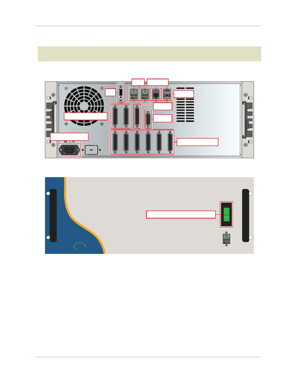
Motor, power, control and position feedback cable connections are made to the rear of the HEXRC.
MOTOR / FEEDBACK
DIGITAL / ANALOG IO MPGA
DVI
USB2 USB3 ETHERNET FIREWIRE
ESTOP
1 2
1 2
3 4 5 6
ESTOP
DVI
Motor / Feedback
Digital / Analog I/O
MPGA
Firewire
AC Power Input
USB Ethernet
Figure 2-1: Power and Control Connections
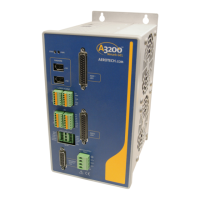
ON
OFF
AEROTECH.
COM
0
A
HEX RC
Powered by
3
2
0
USB
Power Switch / Circuit Breaker
Figure 2-2: Power Switch
All low voltage connections must be made using cables and wires sized for the maximum currents that will
be carried. Low voltage wiring should not be bundled with AC and motor wiring to minimize signal
disturbances due to EMI interference and coupling.
12 Chapter 2 www.aerotech.com