HEXRCHardware Manual Installation and Configuration
2.3.1.3. Encoder Phasing
Incorrect encoder polarity will cause the system to fault when enabled or when a move command is issued.
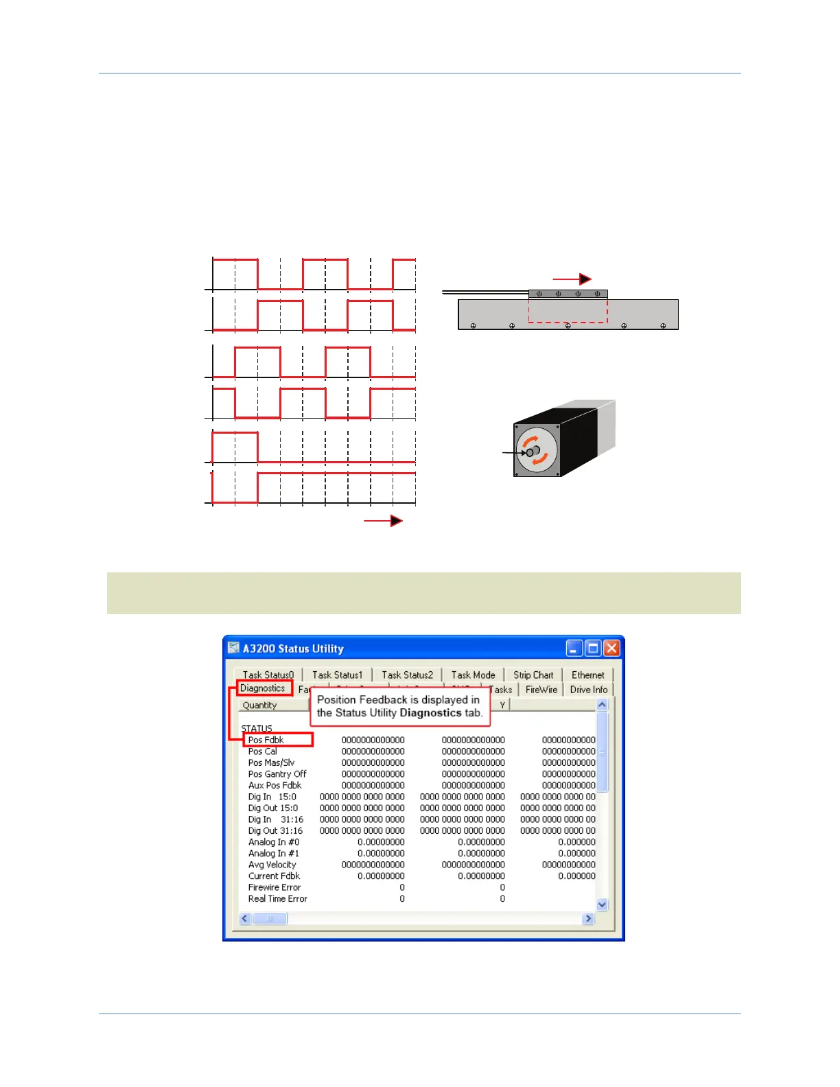
Figure 2-6 illustrates the proper encoder phasing for clockwise motor rotation (or positive forcer movement
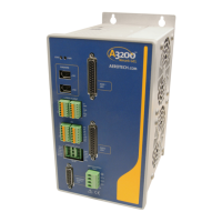
for linear motors). To verify, move the motor by hand in the CW (positive) direction while observing the
position of the encoder in the diagnostics display (see Figure 2-7). The MotorPhasing Calculator in the
Configuration Manager can be used to determine proper encoder polarity.
SIN
SIN-N
COS
COS-N
MRK
MRK-N
Positive MOVE (Clockwise)
Forcer Wires
ForcerMagnet Track
Motor Mounting
Flange (Front View)
Motor Shaft
CW Rotation
(Positive Direction)
LINEAR MOTOR
ROTARY MOTOR
Positive MOVE
(Clockwise)
0° 90° 180° 270° 360° 450° 540° 630° 720° 810°
0° 90° 180° 270° 360° 450° 540° 630° 720° 810°
0° 90° 180° 270° 360° 450° 540° 630° 720° 810°
Figure 2-6: Encoder Phasing Reference Diagram (Standard)
N O T E : Encoder manufacturers may refer to the encoder signals as A, B, and Z. The proper phase rela-
tionship between signals is shown in Figure 2-6.
Figure 2-7: Position Feedback in the DiagnosticDisplay
20 Chapter 2 www.aerotech.com