Installation and Configuration HEXRCHardware Manual
Powered Motor Phasing
Refer to the Motor Phasing Calculator in the Configuration Manager for motor, Hall, and encoder phasing.
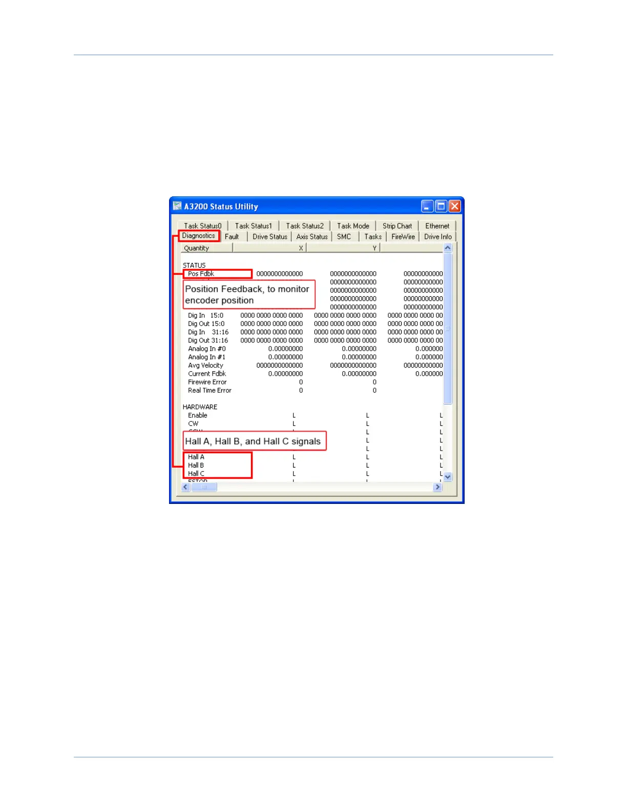
Feedback Monitoring
The state of the encoder and Hall-effect device signals can be observed in the Status Utility.
An “L” for the given Hall input indicates zero voltage or logic low, where a “H” indicates 5V or logic high.
Figure 2-14: Encoder and Hall Signal Diagnostics
www.aerotech.com Chapter 2 27