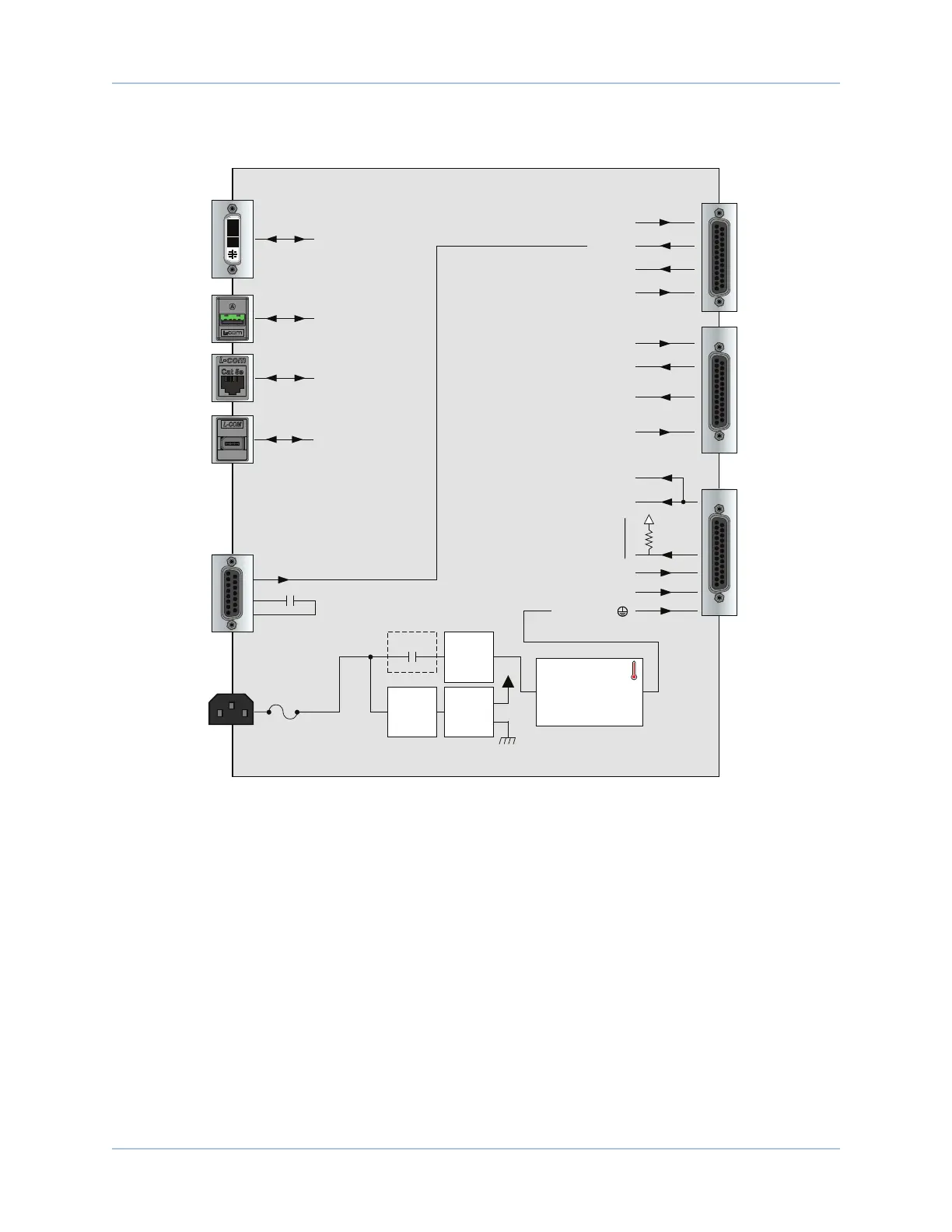
HEXRCHardware Manual Introduction
The following block diagram illustrates the features and options of the HEXRC.
Encoder +5V / Common
Analog Input 0 ±
SIN, COS, MRK
-MXU
MOTOR OUTPUT/
FEEDBACK
(up to x6)
CW, CCW, Home Limits;
Encoder Fault; Hall A, B, C;
Motor Over Temperature
Amplifier
Control
Power
Motor
Power
ESTOP
AC Power
Input
Amplifier
Heatsink Over
Temperature
ESTOP
(optional)
Switch
Control
Power
Supply
Analog Input 1 ±
Analog Output 1
8 Opto Outputs
(Sinking or Sourcing)
8 Opto Inputs
(Sinking or Sourcing)
DIGITAL /
ANALOG IO
(up to x2)
SIN, COS
5V, COM
ESTOP
24V, COM
MPGA
(Option)
FireWire PortCommunications
Ethernet PortCommunications
USB (x3)Communications
Video PortDVI
Motor (+, -, )
Figure 1-2: Functional Diagram
4 Chapter 1 www.aerotech.com