Installation and Configuration HEXRCHardware Manual
2.3. Motor Feedback Connections
The motor feedback connector (a 25-pin, D-style connector) has connections for an encoder, limit switches,
Hall-effect devices, motor over-temperature device, 5 V encoder and limit power, and motor connections.
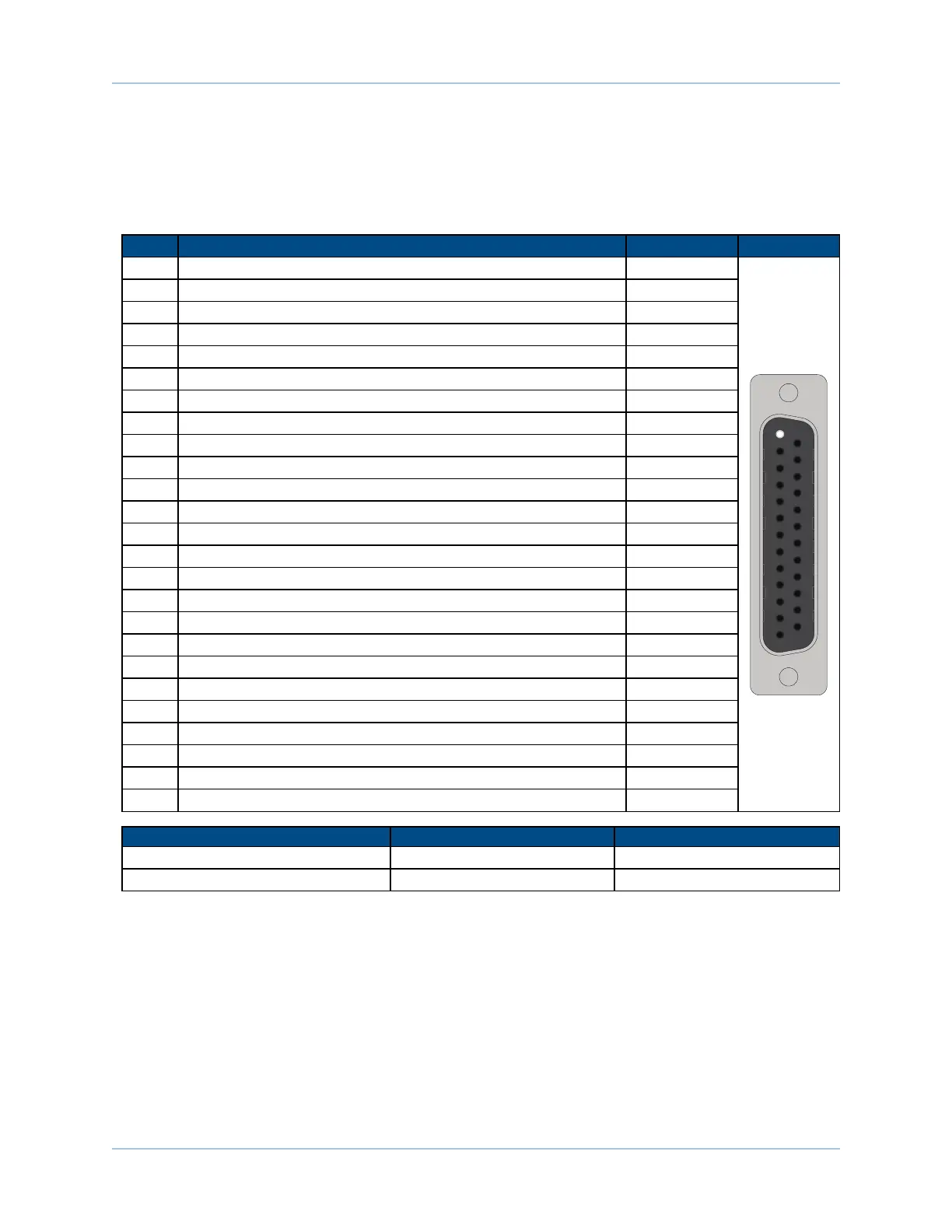
Table 2-5: Motor Feedback Connector Pin Assignment
Pin# Description In/Out/Bi
Connector
1 Key (Ensures that correct cable is plugged into the correct jack) Input
2 Cosine-N Input
3 Sine-N Input
4 Marker-N Input
5 Common --
6 Common --
7 Negative (CCW) hardware limit Input
8 Hall Effect sensor, phase A Input
9 Hall Effect sensor, phase C Input
10 Frame ground --
11 Motor ØA Output
12 Motor ØB Output
13 Motor ØC Output
14 Cosine Input
15 Sine Input
16 Marker Input
17 +5V power supply Output
18 Reserved Input
19 Positive (CW) hardware limit Input
20 Motor Thermistor Input
21 Hall Effect sensor, phase B Input
22 Frame ground --
23 Motor ØA Output
24 Motor ØB Output
25 Motor ØC Output
Mating Connector Aerotech P/N Third Party P/N
25-Pin D-Connector ECK00101 FCI DB25P064TXLF
Backshell ECK00656 Amphenol 17E-1726-2
www.aerotech.com Chapter 2 15