HEXRCHardware Manual Installation and Configuration
Unpowered Motor and Feedback Phasing
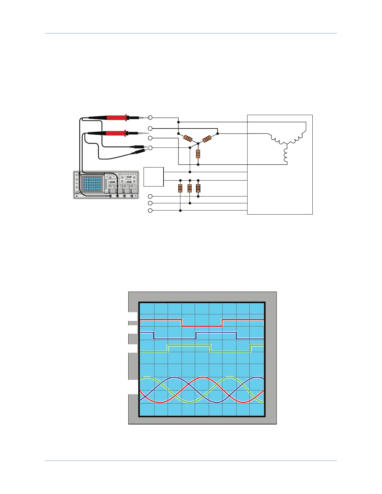
Disconnect the motor from the controller and connect the motor in the test configuration shown in Figure 2-
15. This method will require a two-channel oscilloscope, a 5V power supply, and six resistors (10,000 ohm,
1/4 watt). All measurements should be made with the probe common of each channel of the oscilloscope
connected to a neutral reference test point (TP4, shown in Figure 2-15). Wave forms are shown while moving
the motor in the positive direction.
TP5
TP4
COM
+5V
COM
+5V
10K OHM
TYP
"Wye"
Configuration
10K OHM
TYP
Motor Lead 3
= ØA
Motor Lead 1 = ØB
Motor Lead 2
= ØC
Power Supply
TP3
TP2
TP1
TP6
TP7
Hall 1
Hall 2
Hall 3
CHANNEL 1
CHANNEL 2
Figure 2-15: Motor Phasing Oscilloscope Example
With the designations of the motor and Hall leads of a third party motor determined, the motor can now be
connected to an Aerotech system. Connect motor lead A to motor connector A, motor lead B to motor
connector B, and motor lead C to motor connector C. Hall leads should also be connected to their respective
feedback connector pins (Hall A lead to the Hall A feedback pin, Hall B to Hall B, and Hall C to Hall C). The
motor is correctly phased when the Hall states correspond to the states at each of the electrical angles
(Figure 2-16). Use the CommutationOffset parameter to correct for Hall signal misalignment.
240° 300° 360°120° 180°60°0°
5 63 421
ØAØBØC ØBØC
+V
+5V
0V
0V
-V
Hall A
Hall B
Motor Back
EMF
Hall C
Figure 2-16: Brushless Motor Phasing Goal
28 Chapter 2 www.aerotech.com