7713395 R2 87
• Tap ENTER.
• Tap the LOCK CROP NAMES button to lock in the changes. The button changes to display EDIT CROP NAMES
as before.
• Tap the BACK icon to return to the START DRYER - MAIN screen.
• Verify that the current crop icon at upper-left corner has changed to the newly selected crop.
B. Enable or Disable Blowers and Burners
Overview
• Dryer configuration is set at the factory. The screen will display ONLY the actual blower/burner rows
(number 1 to number 6) that are in this particular dryer configuration.
• The SETUP - MAIN and BATCH DRYING screens utilize this layout and can show from 1 to 6 blower rows.
• On multiple blower dryers, the blower start time is staggered, starting with the upper-most section (number
1). The BLOWER START DELAY TIMER is factory set for a five second delay.
Note
Increase the default delay time on dryers that have blower soft-starters or VFDs to allow each
blower motor to ramp up to full speed before starting the next motor.
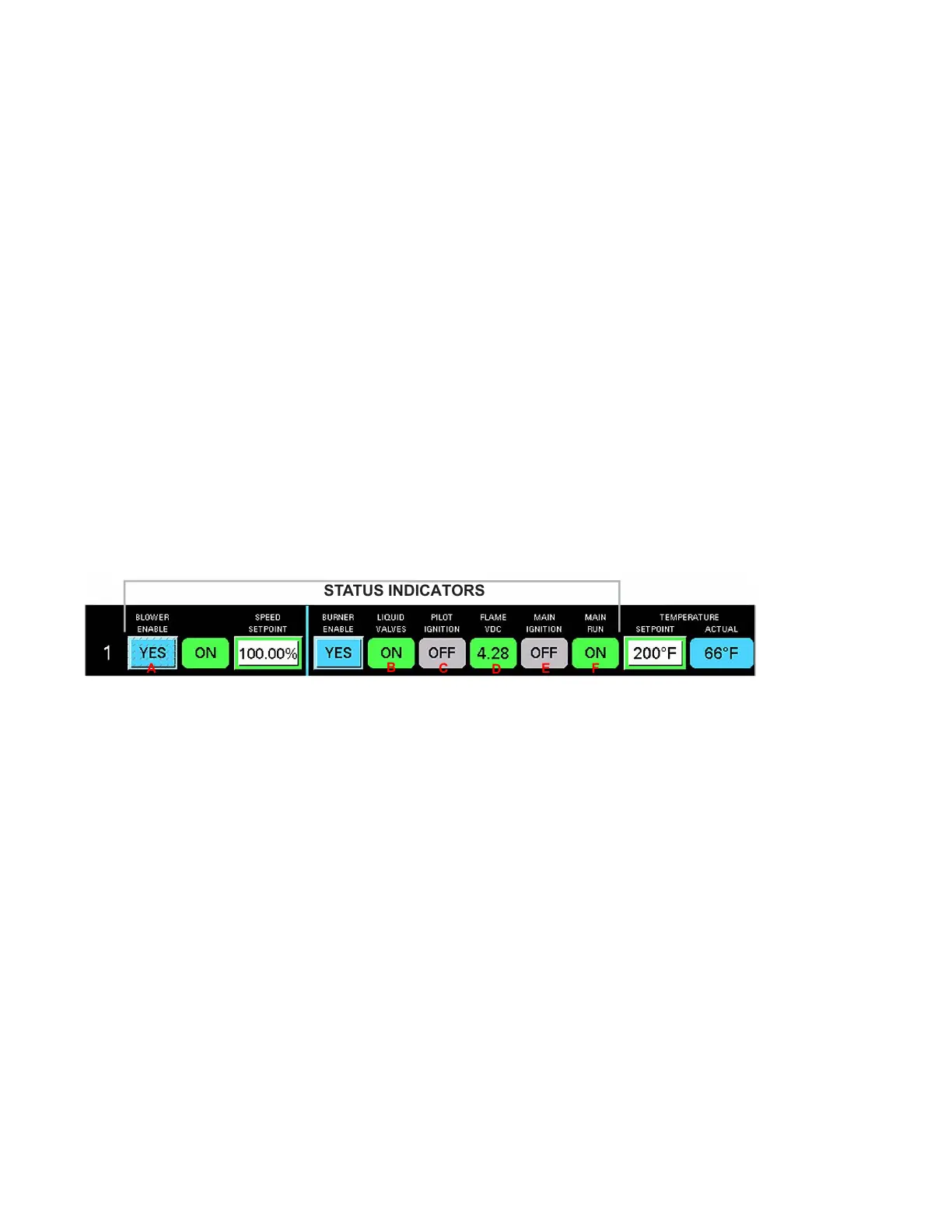
• The ON or OFF status indicators show the current status as either OFF or ON. When the indicator is ON, it
appears to be illuminated.
Figure 102. Status indications (at the end of the startup operation sequence)
Startup Operation Sequence
(A, B, C, D, and E, in the following steps refer to reference letters in Figure 102.)
1. The blower turns ON and the BLOWER indicator changes from OFF to ON (A).
2. The BURNER START DELAY TIMER is factory set for a five second delay. Upon blower ON, the delay timer
starts. When the timer is complete the LP liquid valve opens and the LIQUID VALVE indicator changes from
OFF to ON (B).
3. When LIQUID VALVE goes ON, the valve remains open and purges for a set time of 30 seconds. During this
time the BLOWER is ON, but the pilot valve and main valve (M1) remain closed.
4. At the end of the purge period, the pilot valve and M1 valve opens. The spark generator energizes to light
the pilot. The PILOT IGNITION indicator changes from OFF to ON (C)
5. When the spark generator creates a pilot flame, the flame sensor voltage appears in the FLAME VDC
indicator field (D). If the voltage is 1.25 volts or less the pilot flame is not recognized and an error occurs.
6. After a factory set 10-second period to verify pilot flame, the M2 valve opens.
7. Upon M2 valve opening, a factory set 10–second delay begins.
8. If the air switch does NOT detect blower operation, OR the UV sensor does NOT verify the presence of
burner flame, an error occurs. When the UV sensor does detect the burner flame, the main ignition indicator
changes from OFF to ON (E).
CONTINUOUS MIXED-FLOW GRAIN DRYER WITH COMMANDER CONTROL SYSTEM 4. OPERATION