EasyManuals Logo

Allen-Bradley MicroLogix 1100 User Manual

Allen-Bradley MicroLogix 1100
256 pages
To Next Page IconTo Next Page
To Previous Page IconTo Previous Page
Page #115 background imageLoading...
Page #115 background image
Publication 1763-UM001E-EN-P - June 2015
Using the LCD 113
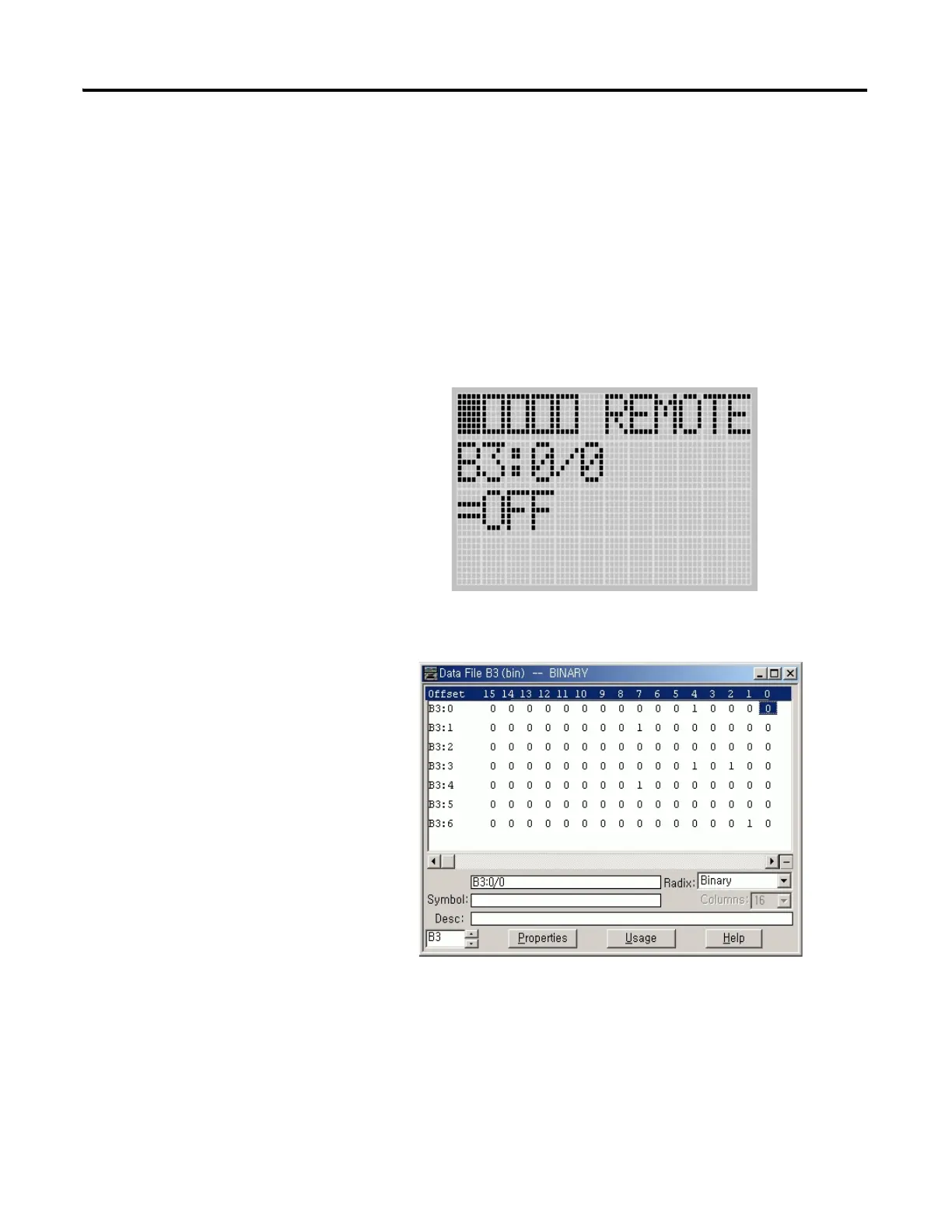
5. We will change the data value of the B3:0/0 bit to OFF (0).
First, press OK to select the displayed address and move the cursor to
the data value position. Then, “ON” will be flashing, which means the
cursor is at the data value position.
6. Press the Down key. Then, the data value will be represented as “OFF”.
Note that “OFF” is still flashing, which means the cursor is still at the
data value position.
7. Press OK to apply the changes. Then, the new value OFF (0) is applied.
Note that the target bit, “0/0” in this example, is flashing. The cursor is
moved automatically to the target bit position.
You can identify this change of data value is reflected to your RSLogix
500 programming software.

Table of Contents

Other manuals for Allen-Bradley MicroLogix 1100

Questions and Answers:

Question and Answer IconNeed help?

Do you have a question about the Allen-Bradley MicroLogix 1100 and is the answer not in the manual?

Allen-Bradley MicroLogix 1100 Specifications

General IconGeneral
Processor32-bit
Programming SoftwareRSLogix 500
MountingDIN rail or panel mount
Power Supply24V DC
TypeCompact PLC
Digital Inputs12
Digital Outputs8
Analog Inputs4 (depending on model)
Analog OutputsOptional with expansion module
Programming LanguageLadder Logic
Operating Temperature0 to 55 °C (32 to 131 °F)
SeriesMicroLogix

Related product manuals