EasyManuals Logo

Allen-Bradley MicroLogix 1100 User Manual

Allen-Bradley MicroLogix 1100
256 pages
To Next Page IconTo Next Page
To Previous Page IconTo Previous Page
Page #53 background imageLoading...
Page #53 background image
Publication 1763-UM001E-EN-P - June 2015
Wiring Your Controller 51
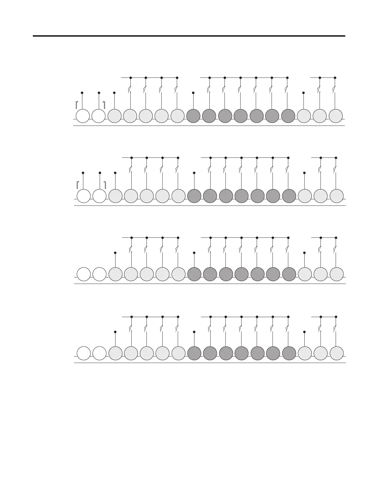
1763-L16BWA Sinking Input Wiring Diagram
1763-L16BWA Sourcing Input Wiring Diagram
1763-L16BBB and 1763-L16DWD Sinking Input Wiring Diagram
1763-L16BBB and 1763-L16DWD Sourcing Input Wiring Diagram
+DCa
-DCa+DC -DC
+DCb
-DCb
L1c
L2c
DC
COM-
DC OUT
+ 24V
I/1I/0 I/2 I/3
DC
COM
I/4 I/5
IA
COM
IV1(+) IV2(+)I/6 I/7 I/8 I/9
24V DC Sensor Power
-DCa
+DCa+DC -DC
-DCb
+DCb
L1c
L2c
DC
COM-
DC OUT
+ 24V
I/1I/0 I/2 I/3
DC
COM
I/4 I/5
IA
COM
IV1(+) IV2(+)I/6 I/7 I/8 I/9
24V DC Sensor Power
+DCa
-DCa
+DCb
-DCb
L1c
L2c
DC
COM
NOT
USED
NOT
USED
I/1I/0 I/2 I/3
DC
COM
I/4 I/5
IA
COM
IV1(+) IV2(+)I/6 I/7 I/8 I/9
-DCa
+DCa
-DCb
+DCb
L1c
L2c
DC
COM
NOT
USED
NOT
USED
I/1I/0 I/2 I/3
DC
COM
I/4 I/5
IA
COM
IV1(+) IV2(+)I/6 I/7 I/8 I/9

Table of Contents

Other manuals for Allen-Bradley MicroLogix 1100

Questions and Answers:

Question and Answer IconNeed help?

Do you have a question about the Allen-Bradley MicroLogix 1100 and is the answer not in the manual?

Allen-Bradley MicroLogix 1100 Specifications

General IconGeneral
Processor32-bit
Programming SoftwareRSLogix 500
MountingDIN rail or panel mount
Power Supply24V DC
TypeCompact PLC
Digital Inputs12
Digital Outputs8
Analog Inputs4 (depending on model)
Analog OutputsOptional with expansion module
Programming LanguageLadder Logic
Operating Temperature0 to 55 °C (32 to 131 °F)
SeriesMicroLogix

Related product manuals