EasyManuals Logo

Allen-Bradley MicroLogix 1100 User Manual

Allen-Bradley MicroLogix 1100
256 pages
To Next Page IconTo Next Page
To Previous Page IconTo Previous Page
Page #69 background imageLoading...
Page #69 background image
Publication 1763-UM001E-EN-P - June 2015
Wiring Your Controller 67
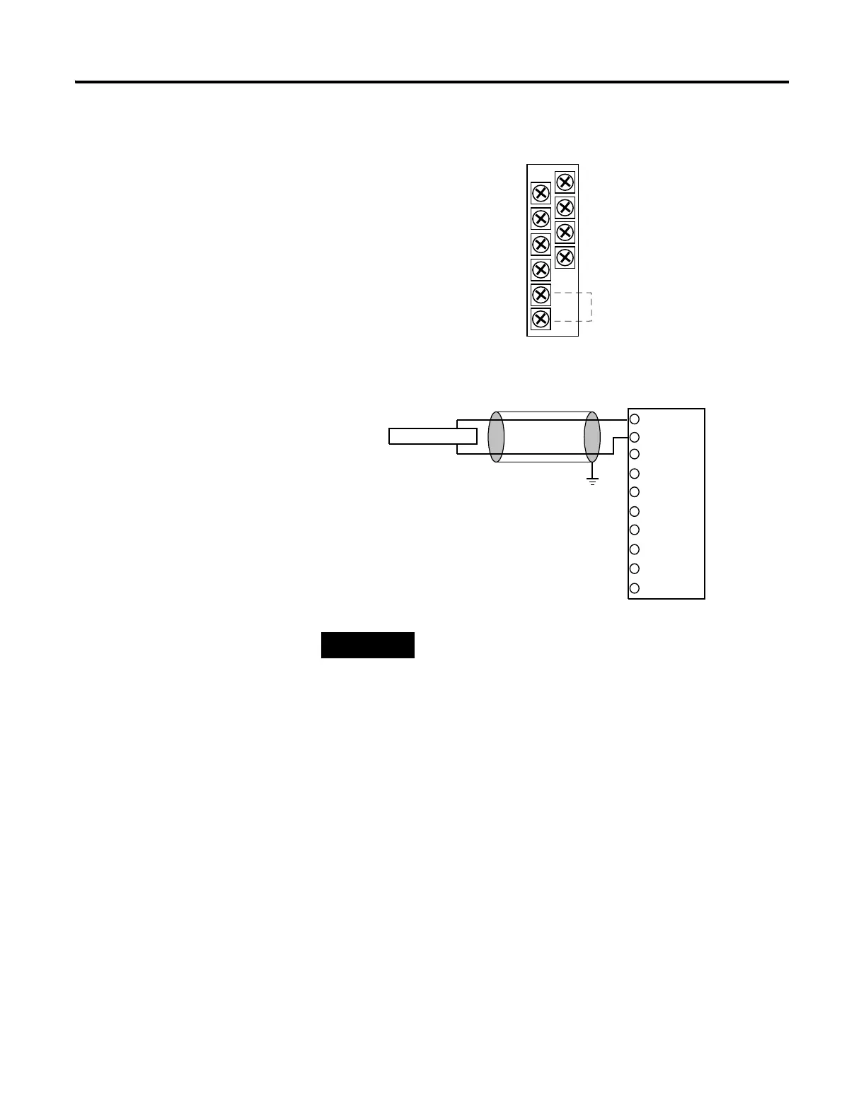
1762-IF4 Terminal Block Layout
Differential Sensor Transmitter Types
TIP
Grounding the cable shield at the module end only
usually provides sufficient noise immunity.
However, for best cable shield performance, earth
ground the shield at both ends, using a 0.01µF
capacitor at one end to block AC power ground
currents, if necessary.
IN 1 (+)
IN 0 (+)
IN 1 (-)
IN 0 (-)
IN 3 (+)
IN 2 (+)
IN 3 (-)
IN 2 (-)
COM
COM
Commons internally connected.
IN 0 (+)
IN 0 (-)
IN 3 (+)
IN 3 (-)
IN 2 (+)
IN 2 (-)
COM
IN 1 (-)
IN 1 (+)
COM
Analog Sensor

Table of Contents

Other manuals for Allen-Bradley MicroLogix 1100

Questions and Answers:

Question and Answer IconNeed help?

Do you have a question about the Allen-Bradley MicroLogix 1100 and is the answer not in the manual?

Allen-Bradley MicroLogix 1100 Specifications

General IconGeneral
Processor32-bit
Programming SoftwareRSLogix 500
MountingDIN rail or panel mount
Power Supply24V DC
TypeCompact PLC
Digital Inputs12
Digital Outputs8
Analog Inputs4 (depending on model)
Analog OutputsOptional with expansion module
Programming LanguageLadder Logic
Operating Temperature0 to 55 °C (32 to 131 °F)
SeriesMicroLogix

Related product manuals