EasyManuals Logo

Allen-Bradley MicroLogix 1100 User Manual

Allen-Bradley MicroLogix 1100
256 pages
To Next Page IconTo Next Page
To Previous Page IconTo Previous Page
Page #70 background imageLoading...
Page #70 background image
Publication 1763-UM001E-EN-P - June 2015
68 Wiring Your Controller
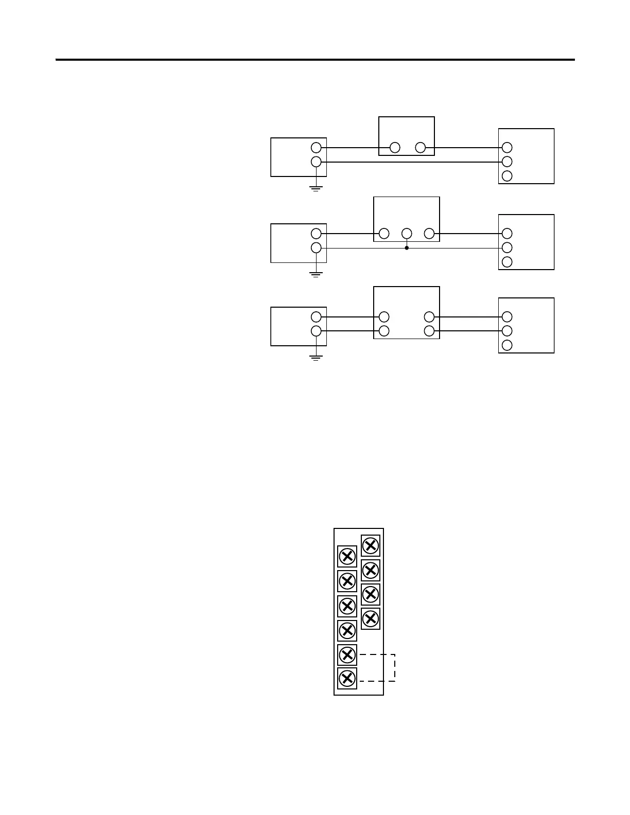
Sensor/Transmitter Types
1762-OF4 Output Type Selection
The output type selection, current or voltage, is made by wiring to the
appropriate terminals, Iout or Vout, and by the type/range selection bits in the
Configuration Data File.
1762-OF4 Terminal Block Layout
+
+
-
-
+
-
+
-
IN +
IN -
COM
+
-
IN +
IN -
COM
+
-
IN +
IN -
COM
Power
Supply
(1)
Power
Supply
(1)
Power
Supply
(1)
Transmitter
Transmitter
Transmitter
Module
Module
Module
Supply Signal
Supply
Signal
2-Wire Transmitter
3-Wire Transmitter
4-Wire Transmitter
(1) All power supplies rated N.E.C. Class 2.
V out 3
V out 2
V out 1
V out 0
I out 3
I out 2
I out 1
I out 0
COM
COM
Commons connected internally

Table of Contents

Other manuals for Allen-Bradley MicroLogix 1100

Questions and Answers:

Question and Answer IconNeed help?

Do you have a question about the Allen-Bradley MicroLogix 1100 and is the answer not in the manual?

Allen-Bradley MicroLogix 1100 Specifications

General IconGeneral
Processor32-bit
Programming SoftwareRSLogix 500
MountingDIN rail or panel mount
Power Supply24V DC
TypeCompact PLC
Digital Inputs12
Digital Outputs8
Analog Inputs4 (depending on model)
Analog OutputsOptional with expansion module
Programming LanguageLadder Logic
Operating Temperature0 to 55 °C (32 to 131 °F)
SeriesMicroLogix

Related product manuals