Chapter 3
Host Computers and Display Terminals
3–6
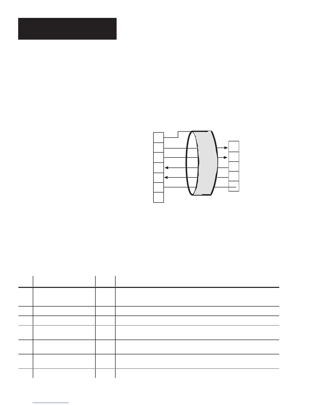
Figure 3.4 shows how to connect the decoder to your host computer using
RS-422. We recommend using Belden (or equivalent) type 9512 cable.
Figure 3.4
Connecting A Host Computer Via RS-422
① When non-metallic connector shells are used. (If cable has a metal connector shell, connect shield to the shell.)
Shield
①
1
14
15
RxA’+
RxB’+
16
17
7
25
COM
TxB+
TxA-
GND
RS-422 TxB+
RS-422 TxA-
RS-422 RxA’-
RS-422 RxB’+
COM
COM
Host Computer Port on
Decoder
Host RS-422 Port
The Display Terminal port is configured as Data Communication Equipment
(DCE). Table 3.B defines which pins of the 25-pin (female) D-shell
connector are used.
Pin Function Abb. Additional Information
1 Protective Ground GND
This pin is electrically bonded to the chassis and to the metal shell of the 25-pin connector.
When plastic shell (non-shielded) connectors are used on the communications cable, the
cable shield drain wire should be connected to this pin.
2 Received Data RxD Serial input data from the display terminal is received on this pin.
3 Transmitted Data TxD Serial output data from the decoder is passed to the display terminal on this pin.
4 Request To Send RTS RTS is an input to the decoder. It may be used to notify the host of a forthcoming
transmission.
5 Clear To Send CTS CTS is an output from the decoder. It is driven to less than -3 VDC whenever the
decoder transmits.
7 Signal Common COM This must be connected to signal common on the display terminal, Pins 1, 7, and 25 are
tied together in the decoder.
25 Signal Common COM See comments for Pin 7.
RS-422 Host Computer Interface
Display erminal Port Pinout
 Loading...


