Chapter 2
Description of Hardware
4–4
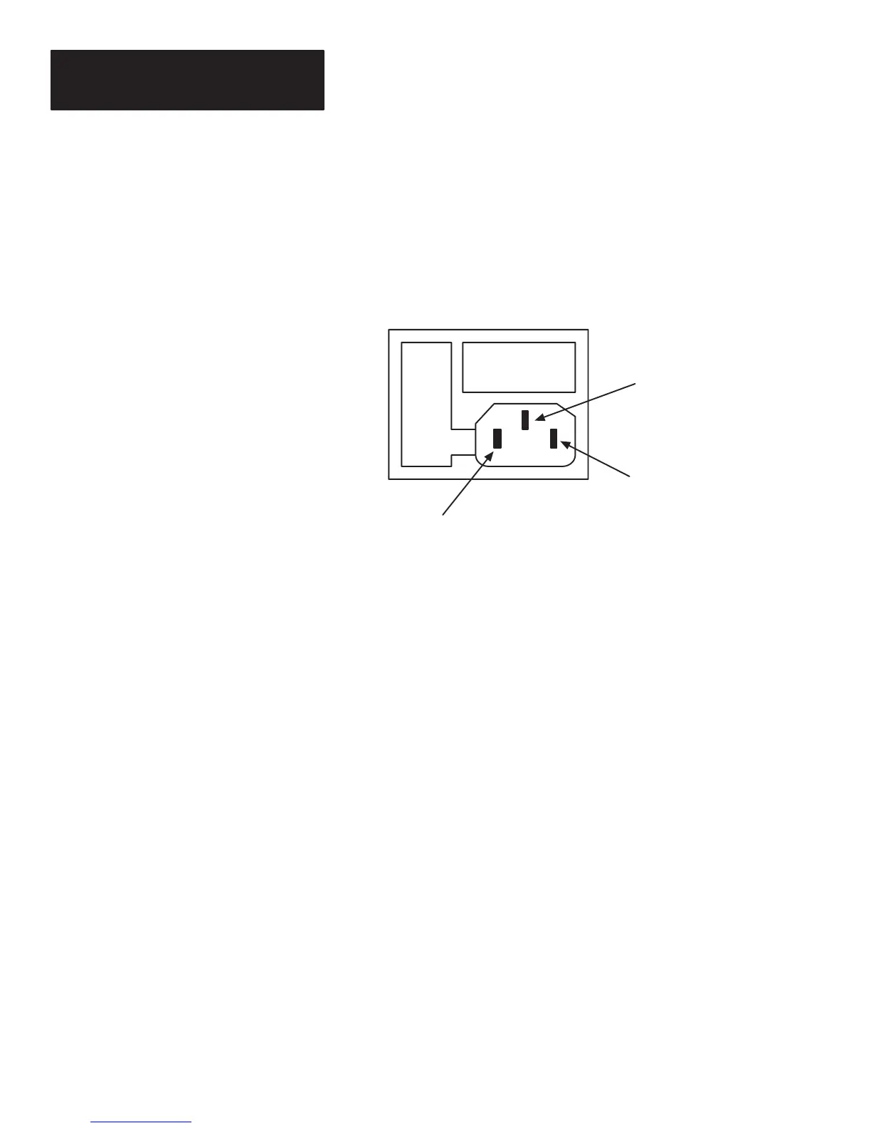
The incoming power connector is a standard IEC 320. This connector is
widely used on computing equipment and instrumentation. Replacement
cables are readily available in different lengths. Figure 4.3 shows the
polarization of the connector.
Figure 4.3
Polarization of the Power Connector
I0
Ground
Line
Neutral
When the decoder is turned ON, the following sequence will occur:
1. The green LED labeled Power will light and remain lit.
2. The decoder resets, ROM/RAM tests are performed, and the decoder is
configured according to the contents stored in EEPROM.
If any of the following messages appear on the connected display terminal,
return your decoder for repair:
EEPROM Self Test Failed
ROM Self Test Failed
RAM Self Test Failed
3. When all tests are passed,
a. The green LED labeled Valid Read will flash once.
b. A single tone will be emitted from the decoder.
If the Laser Connection Detection function is enabled and:
A laser scanner is detected
a. The laser scanner will briefly flash
Incoming Power Cable
Power Up Sequence
 Loading...


