Chapter 3
Host Computers and Display Terminals
3–5
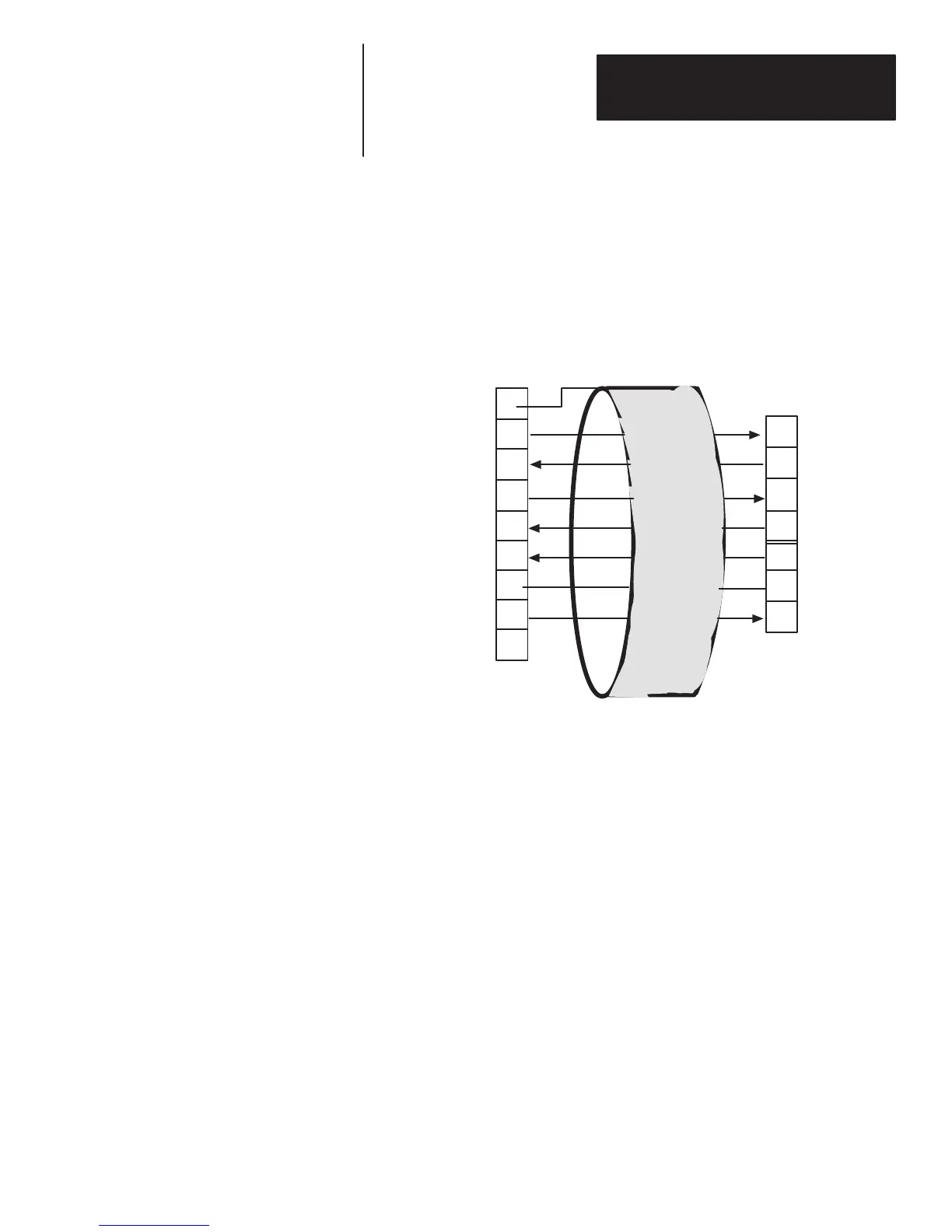
Figure 3.3 shows how to connect the decoder to your host computer using
RS-232-C. We recommend using Belden (or equivalent) type 9363, 9533,
9535, or 9537 cable.
Figure 3.3
Connecting A Host Computer Via RS-232-C
①
DTE = Data Terminal Equipment
②
When non-metallic connector shells are used. (If cable has a metal connector
shell, connect shield to the shell.)
③
Pins 2, 3 and 7 are the minimum connections that can be used. All unused pins
should be left open.
Host Computer Port on
decoder
①
Shield
②
Host RS-232-C
Port
1
2
3
4
5
6
7
20
25
GND
RS-232-C TxD③
RS-232-C RxD③
RS-232-C RTS
RS-232-C CTS
RS-232-C DSR
COM③
RS-232-C DTR
COM
RxD
TxD
CTS
RTS
DTR
COM
DSR
When the host computer wishes to receive data from the local display
terminal, it must set Pin 5 (CTS) on the host computer port to OFF (less than
-3 V). This prevents the decoder from transmitting and insures a clear
channel for communications between the host computer and the local display
terminal.
If the decoder receives data from a scanning device, it will force RTS low
preventing communications between the host and display terminal.
RS-232-C Host Computer
Interface
 Loading...


