118 Rockwell Automation Publication 1560F-UM001A-EN-P - June 2019
Chapter 4 Programming
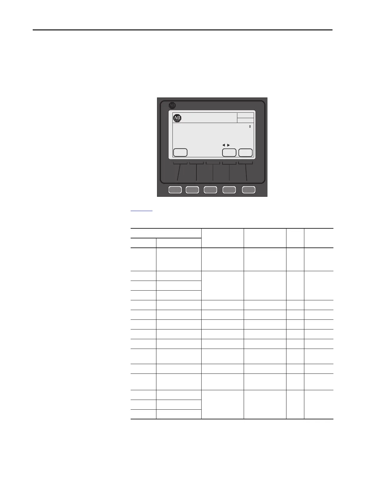
c. Change the bit assignment, then press EDIT.
If the parameter is not bit configured (for example, Turns Ratio):
a. Press the EDIT.
b. Change the value within the displayed limits, then press ENTER to
load the parameter contents into memory.
Table 25
provides the parameter detail of the 150-SM2.
Table 25 - 150-SM2 Parameters
Parameter Min/Max Values Default Value Access Units
Number
(1)
Name
X.1 Module Status Bit 0 = Module Ready
Bit 1 = PTC
Bit 2 = CT Loss
— R Bit = 0
Disable
Bit = 1 Enable
X.2 Fault Enable Bit 0 = PTC
Bit 1 = Ground Fault
— R/W Bit = 0
Disable
Bit = 1 Enable
X.3 Alarm Enable
X.4 Restart Enable
X.5 Turns Ratio
(2)
100…2000 1000 R/W NA
X.6 Ground Fault Level
(3)
0.00…5.00 2.5 R/W Amps
X.7 Ground Fault Delay 0.1…250.0 0.5 R/W Seconds
X.8 Ground Fault A Level 0.00…5.00 2.5 R/W Amps
X.9 Ground Fault A Delay 0.1…250.0 0.5 R/W Seconds
X.10 Ground Fault Inh
Time
(4)
0.0…250.0 10.0 R/W Seconds
X.11 Ground Current 0.00…5.00 0.00 R Amps
X.12 CT Enable Disable
Enable
Disable R/W NA
X.13 CT Scaling A 0.10…5.00 1.00 R NA
X.14 CT Scaling B
X.15 CT Scaling C
PROPERTIES
AUTO
Stopped
0 Amps
Allen-Bradley
ESC
PAR #
Port 07 Host Param 2
Fault Enable
xxxx xxxx xxxx xx00
Bit 01 Ground Fault
EDIT

 Loading...


