158 Rockwell Automation Publication 1560F-UM001A-EN-P - June 2019
Chapter 9 Troubleshooting
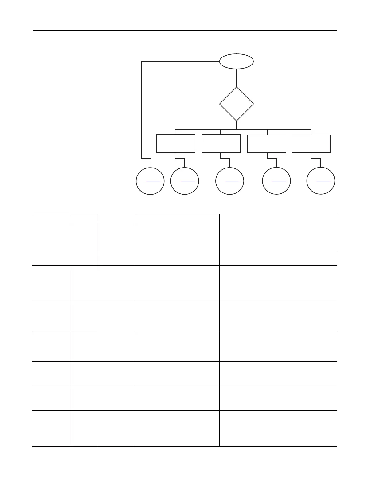
Figure 49 - Troubleshooting Flowchart
See Table 58
See Table 59
See Tab le 6 0
See Tabl e 61
See Tab le 6 2
Yes
No
Fault Displayed?
Define
Nature of
Trouble
Motor will not start.
There is no output
voltage to the motor.
Motor starts but
does not accelerate
to full speed.
Motor stops while
running.
Miscellaneous
situations
Table 58 - Fault Display Explanation
Display Fault Code Fault Enabled Possible Causes Possible Solutions
Line Loss (with phase
indication)
1, 2, 3
Prestart and
Running
• High impedance line connection
• Missing supply phase
• Motor not connected properly
• Incoming 3-phase voltage instability
• Check for line and load loose connections.
• Check for open line (for example, blown fuse).
• Check for open line lead(s).
• Verify power quality.
• Disable this fault/alarm feature.
Shorted SCR (with
phase Indication)
4, 5, 6 In All Modes • Shorted power module.
• Check for shorted SCR, perform a resistance check (see Power
Module Check section), or replace power module if necessary.
Open Gate (with
phase indication)
7, 8, 9 Start or Stop
•Open gate circuitry
• Loose gate lead
• Perform a resistance check (see Power Module Check section),
replace power module if necessary.
• Remove control module from the power section and check gate
lead connections (TB5, TB6, and TB 7) are firmly seated to the
control module.
• Disable this fault/alarm feature.
SCR Overtemp or PTC
Power Pole
10 or 60 In All Modes
• Controller ventilation blocked
• Controller duty cycle exceeded
• Ambient temperature limit exceeded
•Failed thermistor
• Check for proper controller ventilation.
• Check application-appropriate duty cycle.
• Wait for controller to cool or provide external cooling if ambient
temperature is high.
• Replace power module or control module as needed.
Open Bypass 11, 12, 13 In All Modes
• Control voltage is low
• Inoperable power module bypass
• Check control voltage power supply.
• Replace power module.
• Check control module TB2…TB4 and TB5…TB7 for proper order
and secureness.
• Make sure that no auxiliary contact is set to “external bypass”.
No Load or Open
Load (with Phase
Indication)
14, 15, 16, 17 Prestart Only
• Loss of load side power wiring with phase
indication (15=A, 17=C)
• Start command cycled unexpectedly with
motor rotating
• Check all load side power connections.
• Check motor windings (insulation resistance test).
Voltage Unbalance or
Current Imbalance
18 or 42 Running
• Power line unbalance is greater than the
programmed value
• The delay time programmed is too short for
the application
• Check the power system and correct if necessary or change the
programmed value.
• Extend the delay time to match the application requirements.
• Disable this fault/alarm feature.
Overvoltage 19 Running
• Power line grid voltage is greater than the
programmed value
• Abnormal voltage regulation
• The parameter settings and/or delay time
programmed are not suited for the
application
• Check the power system and correct if necessary. NOTE: If the
power source is a backup generator, check the stability of the
generator voltage regulator. Replace if necessary.
• Modify the parameter and/or extend the delay time to match the
application requirements.
• Disable this fault/alarm feature.

 Loading...


