Rockwell Automation Publication 1560F-UM001A-EN-P - June 2019 175
Troubleshooting Chapter 9
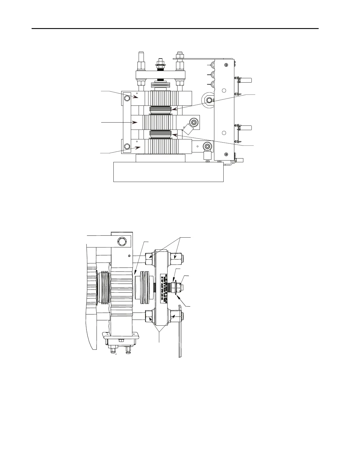
Figure 53 - Power Module Assembly (one phase) • 1000/1300/1500/2400V, 180/360A
Figure 54 - Heatsink Clamp
Heatsink 1
Heatsink 3
Heatsink 2
SCR 2
SCR 1
(Do not loosen)
Gap
Center Nut
Locking Nut
(Do not adjust)
Indicating Washer
(Do not loosen)
To remove clamp pressure, loosen lower
center nut so that the gap between the
clamp surface and the heatsink is
approximately 6 mm (0.25 in.).

 Loading...


