Rockwell Automation Publication 1560F-UM001A-EN-P - June 2019 225
Parameter Information Appendix A
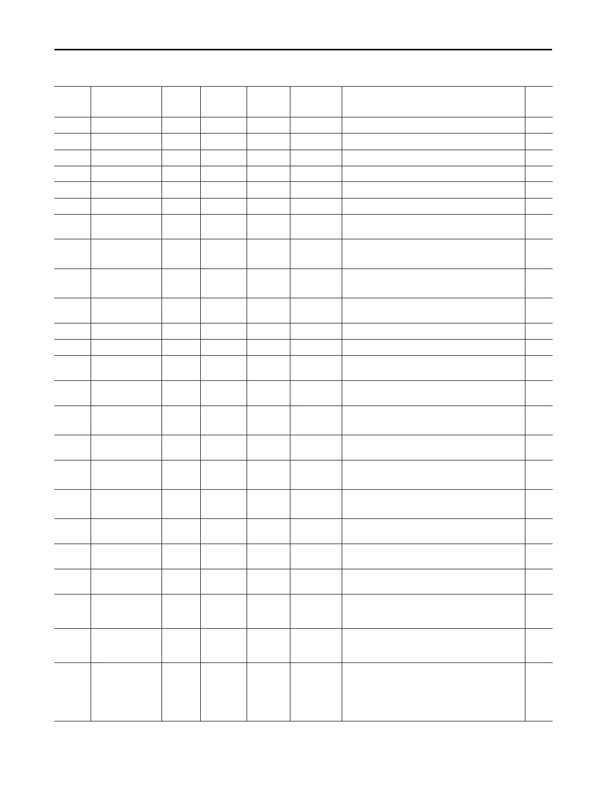
274 Reactive Power A MVAR -1000/1000 0.000 Displays the reactive power of the Phase A branch. R
275 Reactive Power B MVAR -1000/1000 0.000 Displays the reactive power of the Phase B branch. R
276 Reactive Power C MVAR -1000/1000 0.000 Displays the reactive power of the Phase C branch. R
277 Reactive Power MVAR -1000/1000 0.000 Displays the total reactive power. R
278 Reactive Energy C MVARH -1000/1000 0.000 Displays the reactive energy being consumed by the load. R
279 Reactive Energy P MVARH -1000/1000 0.000 Displays the reactive energy being produced by the load. R
280 Reactive Energy MVARH -1000/1000 0.000 Displays the total reactive energy which is equal to Reactive
Power X time.
R
281 Reactive Demand MVAR -1000/1000 0.000 Displays the Reactive Energy consumed or generated by the
system over the Demand Time Period.
R
282 Max. Reactive Dmd MVAR -1000/1000 0.000 Displays the maximum reactive energy demand recorded since
the energy meters were reset
R
283 Apparent Power A MVA -1000/1000 0.000 Displays the Apparent Power (VA) measured in the phase A
branch.
R
284 Apparent Power B MVA -1000/1000 0.000 Displays the VA measured in the phase B branch. R
285 Apparent Power C MVA -1000/1000 0.000 Displays the VA measured in the phase C branch. R
286 Apparent Power MVA -1000/1000 0.000 Displays the total apparent power consumed (-) or produced
(+) by the load.
R
287 Apparent Energy MVAH -1000/1000 0.000 Displays the Apparent Energy which is equal to Apparent Power
x Time.
R
288 Apparent Demand MVA -1000/1000 0.000 Displays the total amount of Apparent Energy which is equal to
MVAH x demand period produced or consumed by the load.
R
289 Max. Apparent Dmd MVA -1000/1000 0.000 Displays the maximum apparent demand recorded since energy
meters were reset.
R
290 Demand Period Mins 1/255 1 Enables the user to enter the time period that energy samples
are taken to calculate demand.
R/W
291 Num of Periods 1/15 1 Enables the user to enter the number of periods that energy
measurements are taken in calculating demand.
R/W
292 Power Factor A -1/1 0.00 Displays the power factor in the Phase A branch of the load
circuit.
R
293 Power Factor B -1/1 0.00 Displays the power factor in the Phase B branch of the load
circuit.
R
294 Power Factor C -1/1 0.00 Displays the power factor in the Phase C branch of the load
circuit.
R
295 Current Imbal % 0/100 0.00 Displays the percent current imbalance measured in the load
circuit (max deviation of current from the average of three
currents / average current of three currents).
R
296 Voltage Imbal % 0/100 0.00 Displays the percent voltage imbalance measured in the load
circuit (max deviation of voltage from the average of three
voltages / average current of three voltages).
R
297 -MVAR Ov F Lvl MVAR -1000/0 0.000 Enables the user to enter a value for the Generated Reactive
Power Over Fault Level (-MVAR Ov F Lvl). If the current actual
value for Generated Reactive Power is more than the -MVAR Ov
F Lvl for a period greater than that defined by -MVAR Ov F Dly, a
-MVAR Ov fault will be signaled.
R/W
Table 66 - SMC -50 Parameter List (Continued)
Number Name Unit Min/Max Default Enum Text Description R/W

 Loading...


