228 Rockwell Automation Publication 1560F-UM001A-EN-P - June 2019
Appendix A Parameter Information
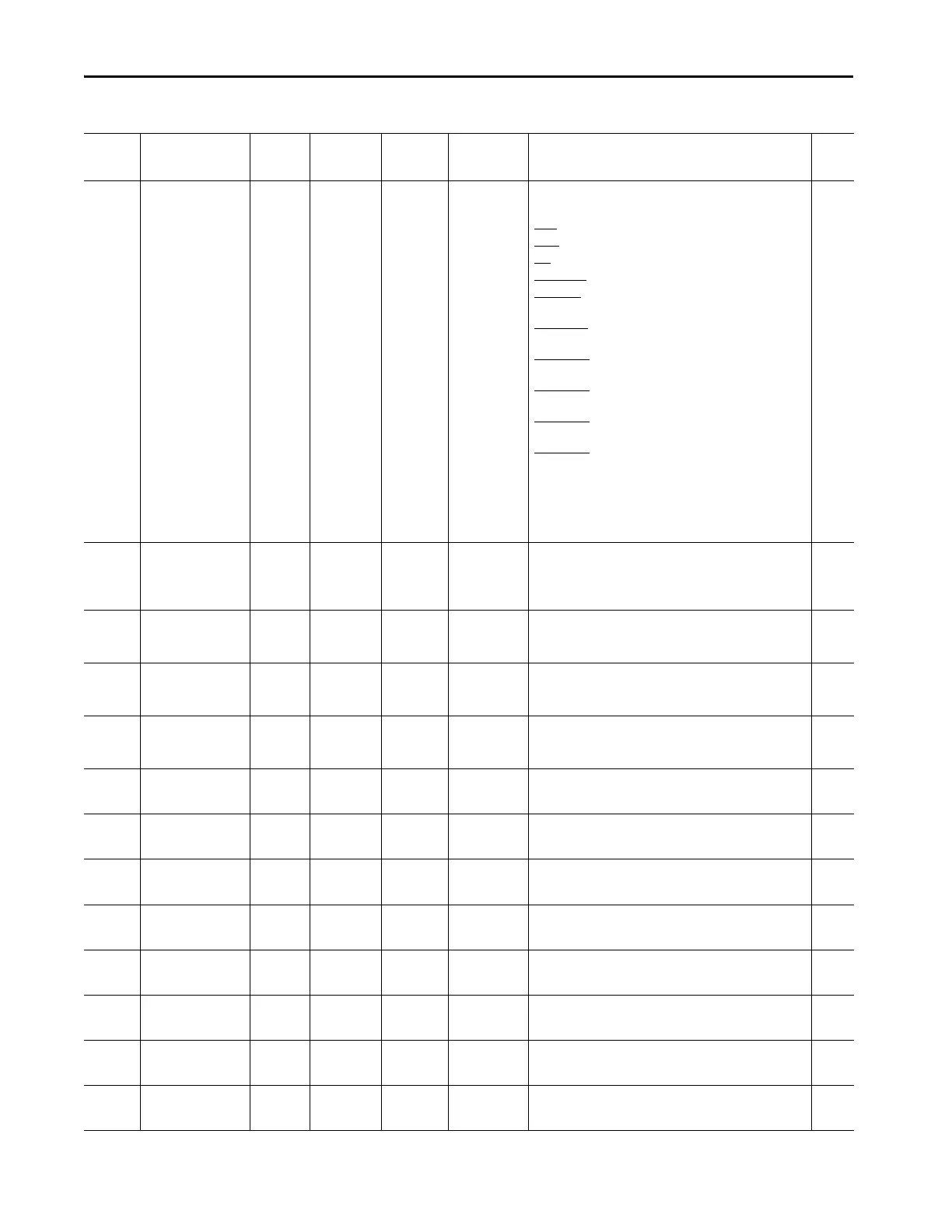
312 Product Command 0/65535 0 Stop
Start
Jog
Clear Fault
Reserved
Emer Run
Reserved
Reserved
Reserved
Reserved
Rserved
Aux Enable
Network_1
Network_2
Network_3
Network_4
Displays an image of the DPI product command required for DPI
communications.
Stop
: 1 - Coast/Inhibit; 0 - No Action;
Start
: 1 - Start; 0 - No Action;
Jog: 1 -Stop Maneuver/Inhibit; 0 -No Action;
Clear Fault
: 1 -Clear Faults; 0 - No Action;
Emer Run: 1 - Enable Emergency Run Mode; 0 - Disable
Emergency Run Mode;
Aux Enable: 1 -Use the Network #1 - #4 bits; 0 -Ignore the
Network #1 - #4 bits;
Network_1
: 1 -Closes any Output Configured for "Network 1";
0 - Opens any Output Configured for "Network 1";
Network_2: 1 -Closes any Output Configured for "Network 2";
0 - Opens any Output Configured for "Network 2";
Network_3: 1 -Closes any Output Configured for "Network 3";
0 - Opens any Output Configured for "Network 3";
Network_4
: 1 -Closes any Output Configured for "Network 4";
0 - Opens any Output Configured for "Network 4";
R
313 Rebalance Level % 0/100 0 The percentage of motor current imbalance above which the
SMC-50 will rebalance the motor current
R/W
314 Va Peak Volts 0/15000 0 The peak value of the Phase A line to neutral voltage during the
motor start, run, and stop cycle. The value resets to 0 when the
motor starts.
R
315 Vb Peak Volts 0/15000 0 The peak value of the Phase B line to neutral voltage during the
motor start, run, and stop cycle.The value resets to 0 when the
motor starts.
R
316 Vc Peak Volts 0/15000 0 The peak value of the Phase C line to neutral voltage during the
motor start, run, and stop cycle. The value resets to 0 when the
motor starts.
R
317 Ia Peak Amps 0/15000 0 The peak value of the Phase A current during the motor start,
run, and stop cycle. The value resets to 0 when the motor starts.
R
318 Ib Peak Amps 0/15000 0 The peak value of the Phase B current during the motor start,
run, and stop cycle. The value resets to 0 when the motor starts.
R
319 Ic Peak Amps 0/15000 0 The peak value of the Phase C current during the motor start,
run, and stop cycle. The value resets to 0 when the motor starts.
R
320 SSVolts Phas A-B Volts 0/15000 0 Snapshot of the Phase A-B voltage when a fault occurs. The
value is overwritten if a subsequent fault occurs
R
321 SSVolts Phas B-C Volts 0/15000 0 Snapshot of the Phase B-C voltage when a fault occurs. The
value is overwritten if a subsequent fault occurs.
R
322 SSVolts Phas C-A Volts 0/15000 0 Snapshot of the Phase C-A voltage when a fault occurs. The
value is overwritten if a subsequent fault occurs.
R
323 SSCurrent Phas A Amps 0/15000 0 Snapshot of the Phase A current when a fault occurs. The value
is overwritten if a subsequent fault occurs.
R
324 SSCurrent Phas B Amps 0/15000 0 Snapshot of the Phase B current when a fault occurs. The value
is overwritten if a subsequent fault occurs.
R
Table 66 - SMC -50 Parameter List (Continued)
Number Name Unit Min/Max Default Enum Text Description R/W

 Loading...


