74 Rockwell Automation Publication 1560F-UM001A-EN-P - June 2019
Chapter 3 Commissioning Procedure
2. Press the "HOLD TO TEST/PUSH TO RESET" push button, located
on the front of the control module, for ten seconds with the motor
stopped. During the next start cycle, the tuning process occurs. The
control module’s status LED will flash amber, indicating that Tuning
occurs on the next start cycle. OR
3. When the control module processes a "Load Factory Defaults" command
via Parameter Management, Parameter 229.
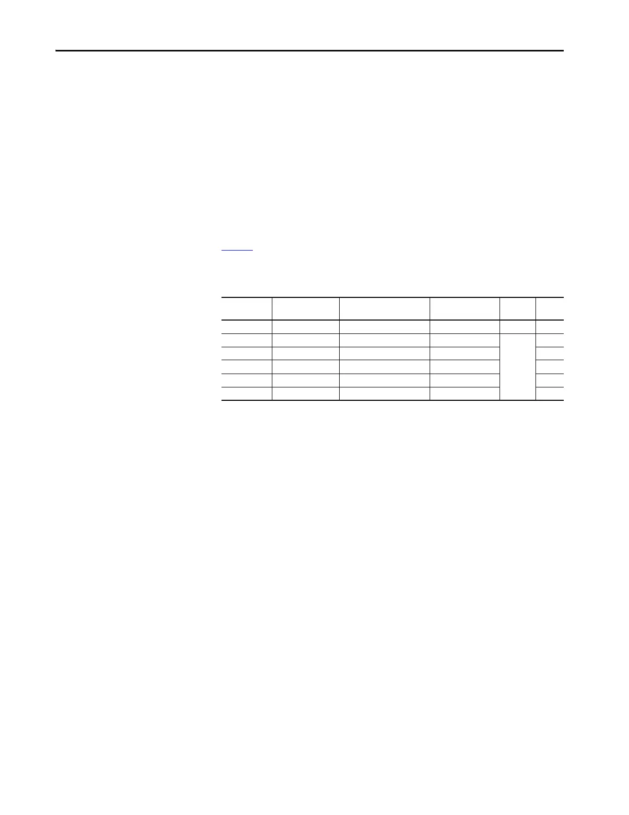
Table 6
lists Parameter 194 Force Tuning along with the key motor parameters
checked by the SMC-50 control module during a motor tuning cycle.
Table 6 - Key Motor Parameters Checked During a Motor Tuning Cycle
TIP If a motor that is smaller or larger than normal is used for initial system
testing, you must perform a motor tuning cycle on the motor used in the
final installation.
Parameter
Number
Parameter Name
Minimum/Maximum
Values
Default Value Access Units
194 Force Tuning FALSE/TRUE TRUE R/W —
195 Stator R 0.00…50.00 0.00…50.00
R
Ohms
196 Total R 0.00…50.00 0.00…50.00 Ohms
197 Coupling Factor 0.00…10.00 0.00…10.00
198 Inductance 0.00…1000.00 0.00…1000.00 mH
45 Motor Connection Line/Delta Line —

 Loading...


