78 Rockwell Automation Publication 1560F-UM001A-EN-P - June 2019
Chapter 3 Commissioning Procedure
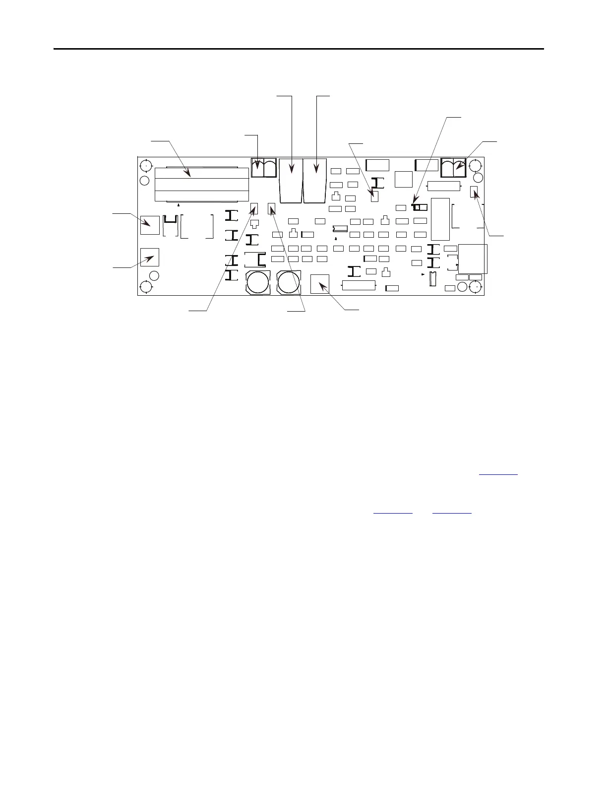
Figure 38 - Test Power Application on Gate Driver Board
8. The yellow LED on the upper right-hand side of the energized gate driver
circuit should be lit (it may appear dim, depending on ambient light
conditions). While the gate pulses are still on, check the voltage on each
gate driver board as described in step 4 above. The voltage should be
10…12V DC. If the voltage is less than 5V, then you have a bad gate drive
board. Do not leave the Portable Test Power Supply connected to a bad
gate driver board. The power supply adapter will burn up if the gate driver
board is shorted.
9. A more detailed check is performed by verifying the actual gate pulses by
connecting an oscilloscope between TP1 and TP3 (-) (see Figure 38
). To
check gate pulses, the pulse generator must be enabled (i.e. SW2 toggled
up) and the Portable Test Power Supply should be connected to J1. The
pulse should appear as shown in Figure 39
and Figure 40.
Temperature signal fiber-
optic transmitter
Gate signal fiber-
optic receiver
Plug-in test
power supply
Current loop CT
Snubber
terminal
Cathode
terminal
Common
test point
+20V test point
+5V test point
Yellow LED
Thermistor
connector
Gate signal
test point
Overvoltage
sense terminal
J3
J4
J1
TP3 TP4
TP2
TP1
J2
RX2RX1
J6

 Loading...


