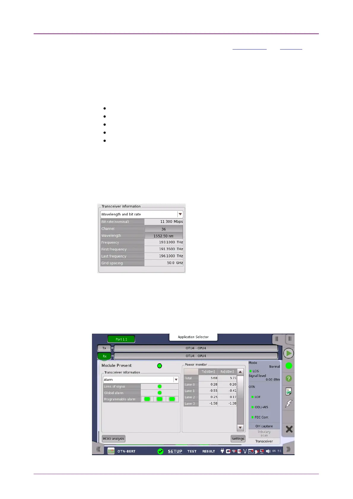
Module PresentModule Present
TransceiverTransceiver
InformationInformation
Power monitorPower monitor
When the optical transceiver is QSFP+ or QSFP28, I2C analysisI2C analysis and SettingsSettings
appear.
Green indicates that an optical transceiver is currently mounted.
Select the information from pull down menu. AlarmAlarm and Output controlOutput control appear
in case of OTU3 and OTU4.
AlarmAlarm shows the alarm status.
Wavelength and bit rateWavelength and bit rate shows the nominal wavelength and bit rate.
ComplianceCompliance shows the available standards.
Vendor informationVendor information shows the data stored in the optical transceiver.
Output controlOutput control allows to select lanes to insert alarm/errors.
Tune wavelengthTune wavelength
When the optical transceiver is a tunable SFP, following items are displayed for
Wavelength and bit rateWavelength and bit rate.
Bit rate, Channel, Wavelength, Frequency, First frequency, Last frequency,
Grid spacing
Touching ChannelChannel or WavelengthWavelength value opens
the dialog box to set the wavelength.
The optical power read out from the transceiver is displayed.
The transmitting optical power is displayed in left column. The received optical
power is displayed in right column.
In case of OTU3 and OTU4, the total optical power and the optical powers by
each lane are displayed.