Probe SetupProbe Setup
Probe ModelProbe Model
When G0306A, G0306B, or G0382A is connected to Network Master, the
model is displayed. Otherwise, select the model of the Video Inspection Probe.
Tip TypeTip Type
Select the tip type to use.
Test ProfileTest Profile
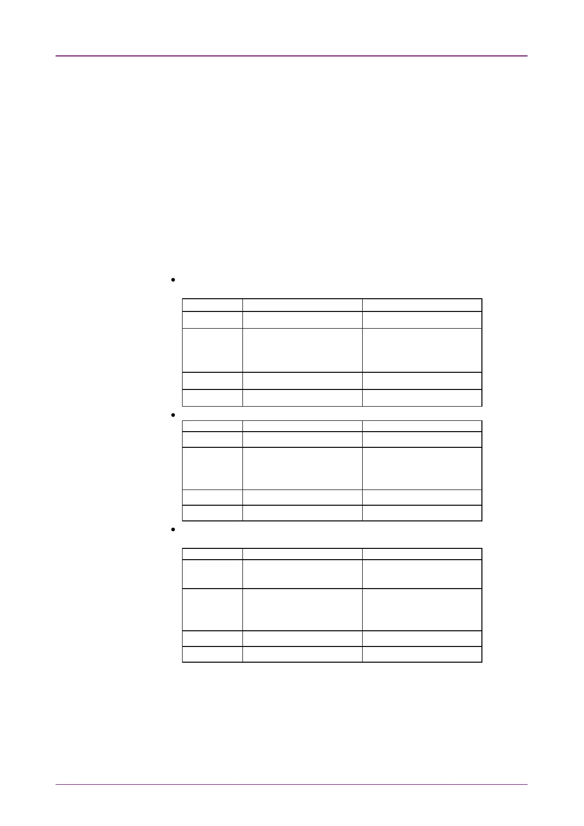
Select the observing fiber type. Limits which will be judged as "Pass" are shown
in tables.
In the following tables, "None" means that the fiber has no scratches or defects.
"No limit" means that there is no limit to the number of scratches or defects.
For example, "None >3 μm" the fiber has no scratches or defects which is
larger than 3 μm.
SM PC>45SM PC>45: Single Mode Fiber, Physical Contact, Return Loss is more than 45
dB.
Zone NameZone Name DefectsDefects ScratchesScratches
Core None None
Cladding
No limit <2μm
5 from 2 μm to 5 μm
None >5 μm
No limit ≤3μm
None > 3μm
Adhesive No limit No limit
Contact None ≥10 μm No limit
SM APCSM APC: Single Mode Fiber, Angled Physical Contact
Zone NameZone Name DefectsDefects ScratchesScratches
Core None ≤4
Cladding
No limit <2 μm
5 from 2 μm to 5 μm
None >5 μm
No limit
Adhesive No limit No limit
Contact None ≥10 μm No limit
SM PC>25SM PC>25: Single Mode Fiber, Physical Contact, Return Loss is more than 25
dB.
Zone NameZone Name DefectsDefects ScratchesScratches
Core
2 ≤3 μm
None > 3 μm
2 ≤3 μm
None > 3 μm
Cladding
No limit ≤2μm
5 from 2 μm to 5 μm
None >5 μm
No limit ≤3μm
3 > 3μm
Adhesive No limit No limit
Contact None ≥10 μm No limit