6-13 Fan Assembly Replacement Removal and Replacement
6-30 PN: 10580-00303 Rev. D Model MS20xxB MM
6-13 Fan Assembly Replacement
This procedure provides instructions for removing and replacing the Fan Assembly.
Parts:
• 3-72779 – Fan Assembly
Procedure:
1. Open the case as described in Section 6-6 “Opening the Instrument Case” on page 6-14.
2. Remove the PCB assembly from the case front as described in Section 6-7 “PCB Assembly Replacement
(MS202xB and MS203xB)” on page 6-17.
3. Cut and remove the silicone rubber fasteners holding the Fan Assembly to the metal pan. Refer to
Figure 6-20 and Figure 6-21.
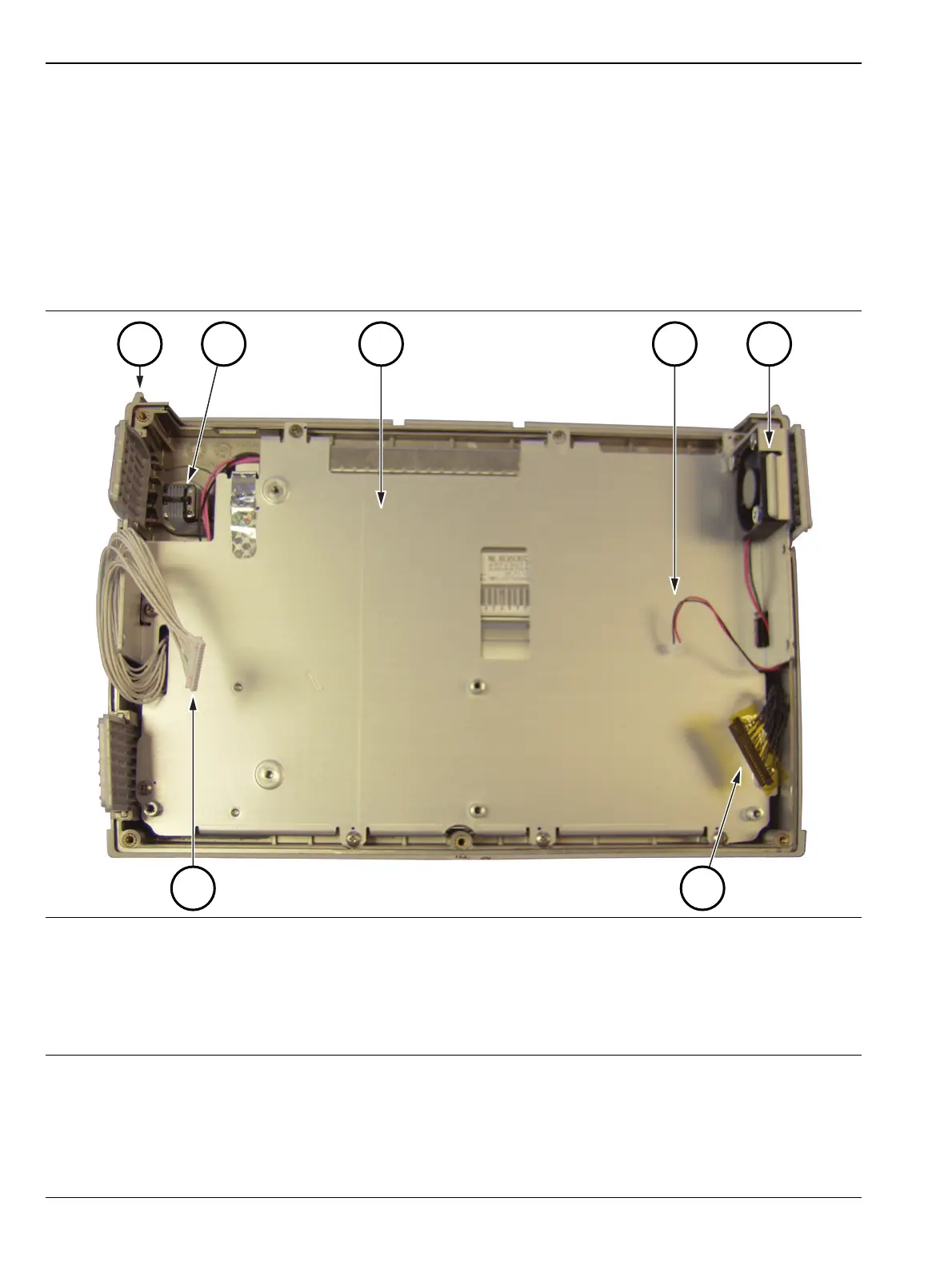
1. Front case assembly
2. Rotary encoder
3. Metal pan securing the LCD assembly
4. Cable connection for fan (cable passes through LCD assembly)
5. Fan assembly
6. Cable connection from LCD to Mother Board
7. Cable connection from keypad to Mother Board
Figure 6-20. Case Front with LCD and Fan

 Loading...


