6-14 LCD Assembly Replacement Removal and Replacement
6-32 PN: 10580-00303 Rev. D Model MS20xxB MM
6-14 LCD Assembly Replacement
This procedure provides instructions for removing and replacing the Liquid Crystal Display (LCD) after the
Main/VNA PCB or Main/VNA PCB/DSP assembly has been separated from the instrument.
Parts:
• 3-15-147 – LCD Display
Procedure:
1. Open the case as described in Section 6-6 “Opening the Instrument Case” on page 6-14.
2. Remove the Main PCB assembly as described in Section 6-7 “PCB Assembly Replacement (MS202xB and
MS203xB)” on page 6-17.
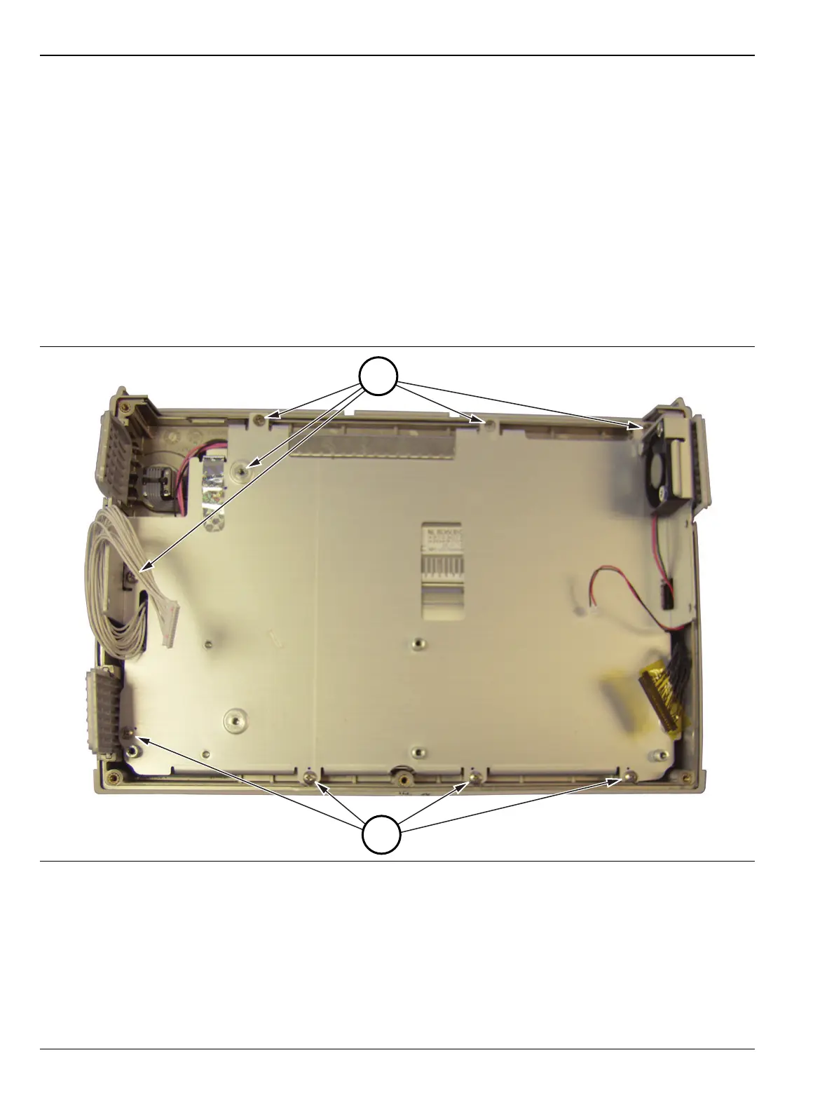
3. Remove the 9 screws securing the metal pan (part of LCD Assembly) to the front half of the case. The
5 screws noted by number 1 in Figure 6-23 are flathead screws. The 4 screws noted by number 2 in
Figure 6-23 are pan head screws.
4. Turn over the LCD assembly and disconnect the front half of the case from the LCD Assembly
(Figure 6-24) by disconnecting the cable.
Figure 6-23. Nine Screws Secure Metal Pan Over LCD Display

 Loading...


