Spectrum Analyzer Performance Verification 3-8 Resolution Bandwidth Accuracy
Model MS20xxB MM PN: 10580-00303 Rev. D 3-17
3-8 Resolution Bandwidth Accuracy
The following test is used to verify the resolution bandwidth accuracy of the spectrum analyzer in the
MS2034B and MS2035B VNA Master.
Equipment Required
• Synthesized Signal Generator, Anritsu Model MS3692X
• K(m) to N(f) Adapter, Anritsu Model 34RKNF50
• 10 MHz Reference Standard
• RF Coaxial Cable, Anritsu Model 15NN50-1.5C
• BNC(m) to BNC(m) Coaxial Cable (Quantity 2), Anritsu part number 2000-1627-R
• BNC Tee Adapter, BNC(m) to BNC(f)/BNC(f), Anritsu part number 3-2600-2
Procedure
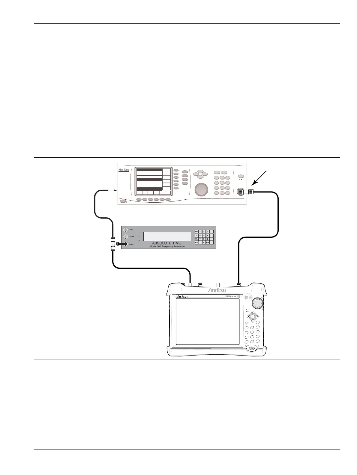
1. Connect the BNC Tee Adapter to the output of the 10 MHz Reference Standard.
2. Connect a BNC Coaxial Cable between the BNC Tee Adapter and the 10 MHz Ref In connector of the
Anritsu MG3692X Synthesized Signal Generator.
3. Connect a BNC Coaxial Cable between the BNC Tee Adapter and the External Ref In connector of the
VNA Master.
4. Turn both the 10 MHz Reference Standard and the Synthesized Signal Generator on.
5. Set the MG3692X RF output frequency to 1 GHz CW and level to –30 dBm.
Figure 3-3. Resolution Bandwidth Accuracy Test
Adapter
10 MHz Reference
MG3692X Source
MS203xB
Power Charge
+/-
.
0
3
Sweep
2
Calibrate
1
Preset
6
Limit
5
Trace
4
Measure
9
Mode
8
System
7
File
Shift
Back
Enter
ESC

 Loading...


