Spectrum Analyzer Performance Verification 3-9 Amplitude Accuracy
Model MS20xxB MM PN: 10580-00303 Rev. D 3-25
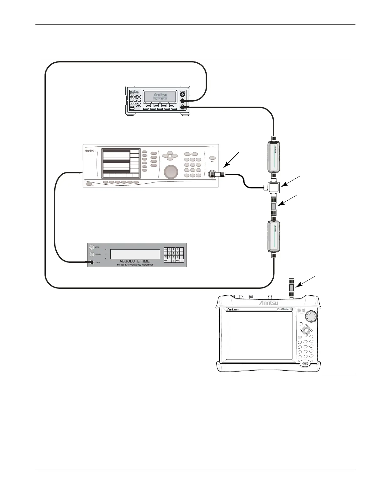
5. Install the 10 dB Fixed Attenuator to the other Power Splitter output and then connect Sensor A to the
end of the attenuator as shown in Figure 3-6.
6. On the power meter, press the Channel front panel key, the Setup soft key and then the Channel soft key
to display Channel 2 Setup menu.
a. Press the Input key twice to set the Input Configuration to B.
b. Press the Sensor key to display both Sensor A and Sensor B readings.
c. Connect the power sensors to the Calibrator port of the power meter and calibrate the sensors.
7. Set the MG3692X frequency to 100 kHz.
Figure 3-6. Fixed Amplitude Level with Varying Frequency Setup
Attenuator
Adapter
10 MHz Reference
Signal Source
Power Meter
Sensor B
Power Splitter
VNA Master
Power Charge
+/-
.
0
3
Sweep
2
Calibrate
1
Preset
6
Limit
5
Trace
4
Measure
9
Mode
8
System
7
File
Shift
Back
Enter
ESC
Adapter
Sensor A

 Loading...


