APEX LOCATOR, through the analysis of the variations of special
electric signals, makes root apex location easier. If used together with a
"file" (not supplied) for manual treatment, it proves useful also to
measure canal length.
Besides using the apex locator in manual mode on this dental unit, this
device can also be used with micromotor "ENDO" mode. The position of
the instruments used on handpieces can be monitored since, through
instrument hoses, APEX LOCATOR signals are directly transferred to
the files, thus allowing to monitor canal position during treatments.
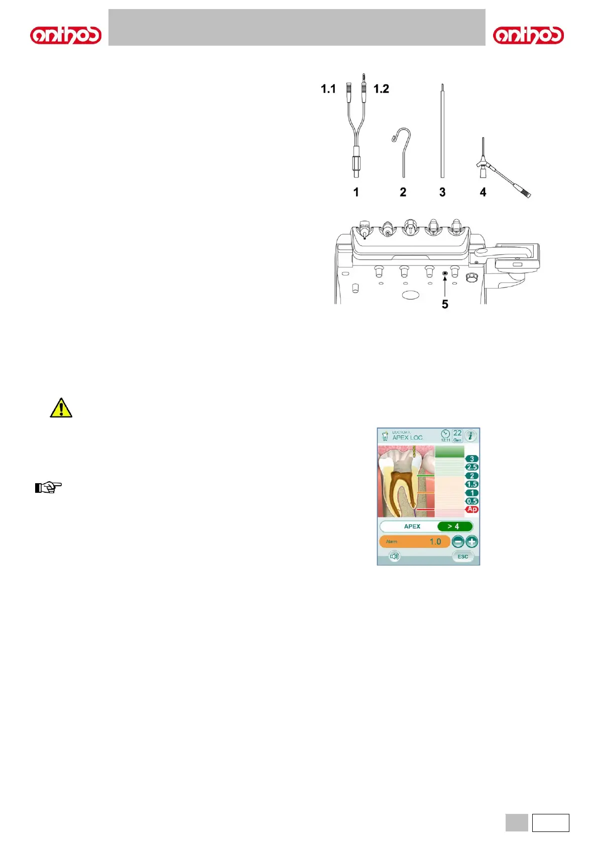
Component description.
1 APEX LOCATOR external wiring.
1.1 APEX LOCATOR external wiring - neutral pole.
1.2 APEX LOCATOR external wiring - active pole.
2 Hook-type electrode.
3 Probe.
4 APEX LOCATOR clip connecting tweezers.
5 APEX LOCATOR external wiring port.
Operation.
• On this dental unit, APEX LOCATOR is automatically activated upon
external wiring ( 1 ) insertion inside the special socket ( 5 ) positioned
under dentist's board.
Once enabled, the menu for alarm threshold setting appears on the
display (see paragraph 5.1.1.2.17.).
• Electrode application:
- Connect hook-type electrode ( 2 ) to neutral pole ( 1.1 ) and
position it on patient's lip.
- Connect active pole ( 1.2 ) to file (not supplied) inserted inside the
root canal; connection to the file can be carried out through probe
( 3 ) or through the special tweezers ( 4 ) or through the special
pre-settings made for handpieces.
Indications on the display.
• The bargraph on display left-hand side indicates file position compared
to apex. The numerical indications "1 2 3" refer to the relative distance
between instrument and apex.
• The APEX icon displays the distance from instrument to apex.
• The ALARM icon displays the set alarm threshold.
The alarm threshold refers to the distance between instrument and
apex above which an audible signal - progressively increasing as
instrument gets closer to apex - is generated.
To set the alarm threshold, see paragraph 5.1.1.2.17.
Both graphic and numerical indications are constantly updated while file
is inserted inside canal.