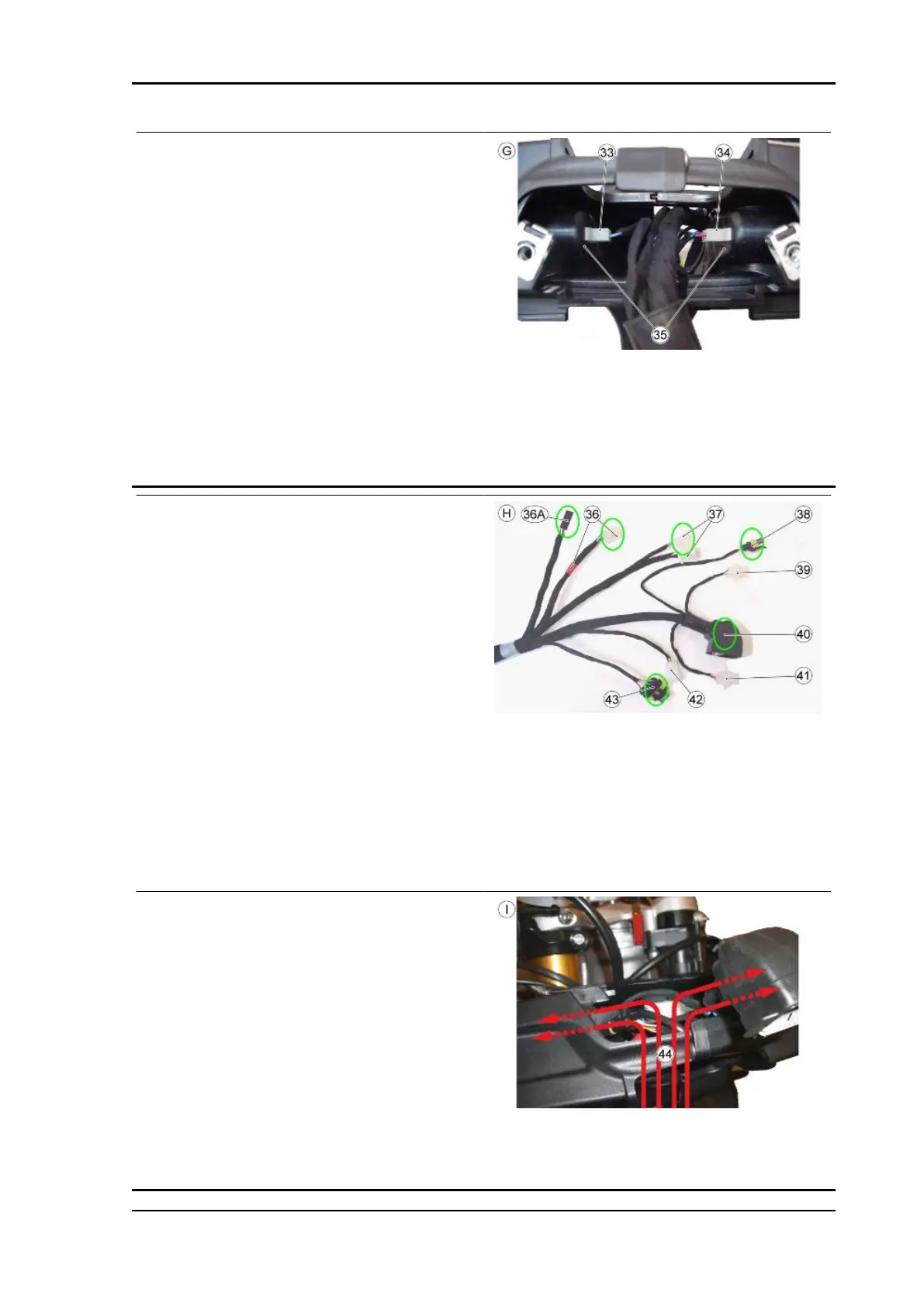
TABLE G - INSTRUMENT HOLDER ARCH
BRACE AND FRONT PART
The left arch brace can now be fit.
After fitting the left arch brace, the clamp used for
holding the cable harnesses inside the arch brace
itself must be cut and removed.
33. Left turn indicator connector (cable colours:
light blue and blue)
34. Right turn indicator connector (cable colours:
red and blue)
35. Insert the connectors into their seats on the
arch brace
TABLE H - INSTRUMENT HOLDER SUPPORT
AND FRONT PART
36. Ignition switch connector (cable harness with
red taping)
36A. Quick Shift control connector
37. Left handlebar control connectors
38. Antenna connector
39. Left turn indicator connector (cable colours:
light blue and blue)
40. Instrument panel connector
41. Right turn indicator connector (cable colours:
red and blue)
42. Front stop switch connector
43. Right handlebar control connector
TABLE I - INSTRUMENT HOLDER SUPPORT
AND FRONT PART
Make the connections for all connectors. The key
switch connector has a longer cable harness in
comparison to the 6 pin connectors for the left light
switch. The cable harness side ignition switch con-
nector is distinguished with red taping on its
branch.
44. Insert the connectors inside the two support
compartments (left and right)
RSV4 Factory a-PRC Electrical system
ELE SYS - 107

 Loading...