RELAY LAYOUT
Component position
in the electrical circuit
diagram
Component name Location on the vehicle
10 Low beam light relay Windshield front part
9 High beam light relay Windshield front part
31 Start-up relay Rear undertail section
19 Protection relay Under the saddle next to the battery, left side
33 Injection relay Under the saddle next to the battery, right side
36 Fan control relay In the niche of the headstock, on the left
25 Recovery logic relay (urgent service) In the niche of the headstock, on the right
Electrical system installation
INTRODUCTION
Scope and applicability
This document aims at defining the cable harness routing in order to achieve the vehicle reliability
targets.
CHASSIS
Materials used and corresponding quantities
The electrical system consists of the following cable harnesses and parts:
•
1 Vehicle cable harness
•
1 Headlamp cable harness
•
1 License plate frame cable harness
•
1 Positive battery cable
•
1 Battery - engine ground cable
•
1 Ignition switch
•
1 ABS speed sensor
•
1 Start-up relay
•
5 Relays
•
1 Protection relay
•
1 Horn
•
1 Fall sensor
•
1 Headlamp
•
1 Taillight
•
1 Instrument panel
•
1 Right rear view mirror with turn indicator
•
1 Left rear view mirror with turn indicator
•
1 Rear right turn indicator
•
1 Rear left turn indicator
•
1 Fuel pump unit
•
1 Stand switch
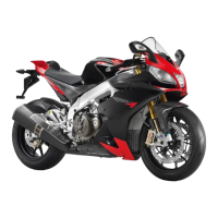
RSV4 Factory a-PRC Electrical system
ELE SYS - 99

 Loading...