VAR8 and Variants Operation, Commissioning, Fault Finding, and Maintenance Guide
sue: 02 complete, approved
-
Is
Page 119 of 166
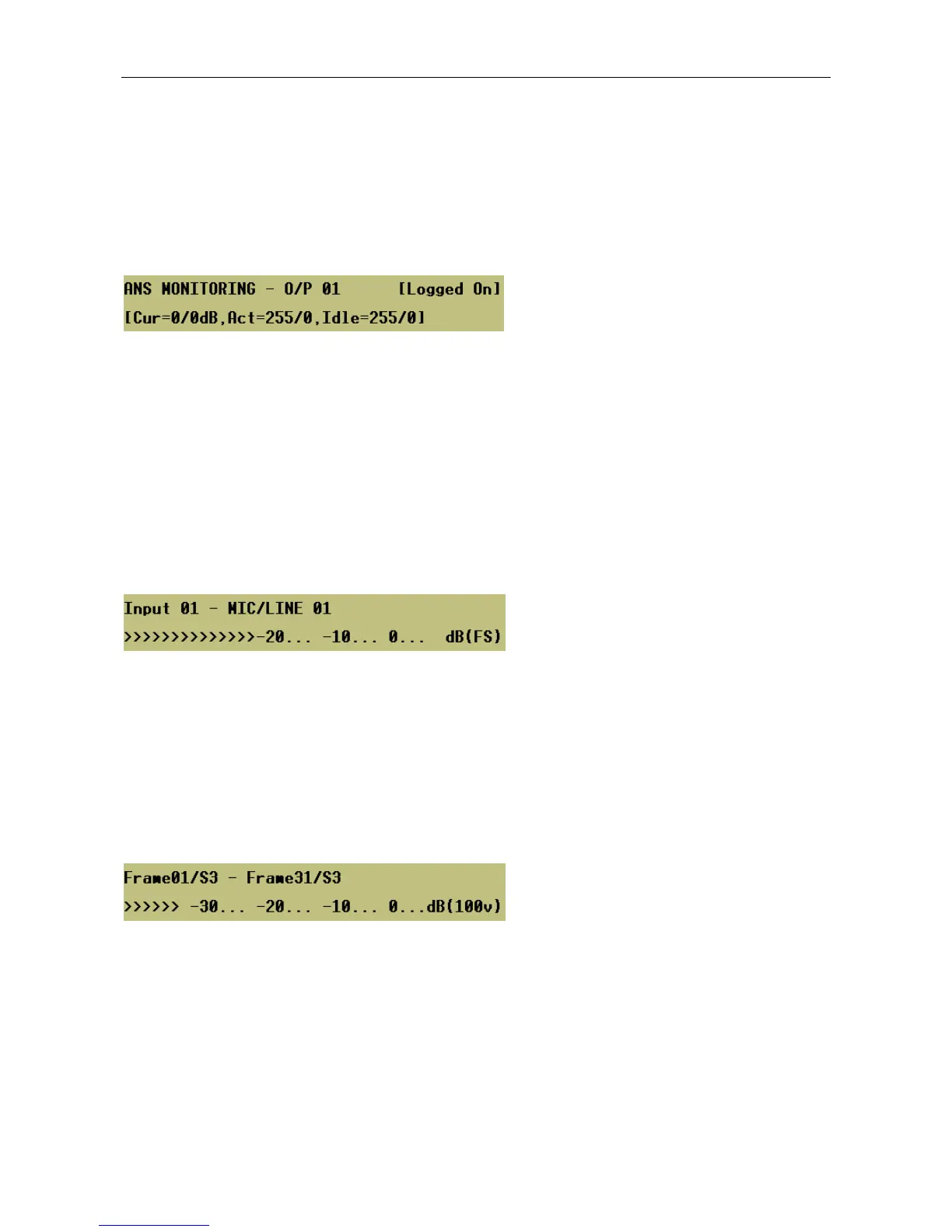
25.3 Viewing the Current Ambient Noise Sensor Readings
The current ambient noise level in a speaker zone monitored by an Ambient Noise Sensor (ANS) may be
read for output level commissioning purpose or for testing when the output level is not within the expected
level.
This test function is only available on the Slave Units via the following menu.
Menu: TestÆMonitorÆANS
Where:
Cur = The current reading (dB) from the ANS sensor / the current attenuation level.
Act = The minimum / maximum readings (dB) from the ANS sensor, with an input routed to the output. It
measures the volume of an announcement.
Idle = The minimum / maximum readings (dB) from the ANS sensor, with nothing routed to the output. It
measures the genuine ambient noise.
25.4 Audio Monitoring
Individual input sources can be monitored on the loudspeaker and a simple bargraph via the following menu.
Menu: TestÆMonitorÆAudioÆInputs
Audio monitoring affects only the LCD display of the unit, i.e. all fault-monitoring activities continue to take
place in the background. The status of the LEDs and external outputs are unaffected.
The level displayed is dB (FS). This is dBs relative to digital Full Scale. Typically the input gain should be set
so that input signal peaks are in the range –10 to –20dB (FS) to allow enough headroom within the Router.
The monitored audio level is adjustable by the rotary encoder. Note that this volume control affects only the
monitor audio level and not the level of the alarm sounder, which shares the same amplifier and speaker.
Individual amplifiers can also be monitored via the following menu.
Menu: TestÆMonitorÆAudioÆOutputs
When monitoring an amplifier, the audio monitor facility actually monitors the audio feeding the speaker
circuit associated with a particular amplifier. If an amplifier has failed and a standby is in operation, then it is
possible to still monitor the audio associated with that speaker circuit, i.e. the audio being monitored is from
the standby amplifier, which is feeding the failed amplifier’s speaker output.
The system remains monitoring whilst within this menu with regular display refreshes and finishes when the
menu times out, the BACK key is pressed, or if any new faults occur.