VAR8 and Variants Operation, Commissioning, Fault Finding, and Maintenance Guide
sue: 02 complete, approved
-
Is
Page 83 of 166
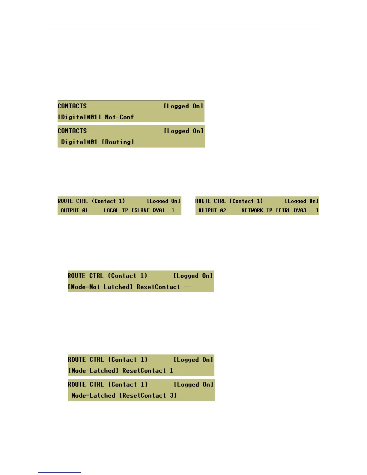
16.1 DVA or Route Trigger via outer Digital Input (Contact)
To Configure a DVA or Route Trigger via Router Contact:
1. Select input and then program it for ‘Routing’.
Menu: ConfigurationÆSystemÆRouterÆCtrlÆContacts
2. Program the combination of outputs and inputs that will be selected when the contact is activated.
Menu: ConfigurationÆSystemÆRouterÆCtrlÆContactsÆDigital#<nn>ÆRoutingÆZoning
Inputs can be any local or Audio Control Unit input, including the Mute input (see Section “12 Mute Input
Configuration”).
Local Input Audio Control Unit (Network)
3. Select the routing mode.
Menu: ConfigurationÆSystemÆRouterÆCtrlÆContactsÆDigital#<nn>ÆRoutingÆControl
ÆLatching
• Not-Latched:
When configured for non-latching operation the activation a ‘Routing’ contact initiates a route. When
the contact is released, the route is cleared.
This mode is useful for the control of both DVA routes and other sources, such as background
music.
This is the system default setting.
• Latched:
A momentary, or prolonged, activation of a ‘Routing’ contact configured for Latched mode initiates a
route; and activating the associated reset contact terminates it unless the corresponding trigger is
still asserted.
This mode is normally used for emergency DVA message routes, but can also be of use for routing
other inputs.
This method is used normally to trigger emergency DVAs although any input source may be routed
in this way. For Fire Alarm DVA messages, BS5839 Pt.8 recommends the use of latched triggers
with separate resets so that the message will continue to run even if the trigger pair fails.