VAR8 and Variants Operation, Commissioning, Fault Finding, and Maintenance Guide
sue: 02 complete, approved
-
Is
Page 160 of 166
30.2 Link Settings for Stand-Alone, 1 or 2 Channel Only Network
Operation
• Please read and observe the “Safety and Precautions” section on page 161 of this manual.
• This procedure is required when the VAR8 is fitted with an ANIC8 Network Interface Card,
and stand-alone operation, or 1 or 2 network channel only operation is required instead of
the default 3 channel network operation.
• If any difficult is found in accessing the links, then please refer to Application Solutions
Limited.
!
!
2. Configure the links as follows:
1. Remove the unit’s lid by undoing the screws
located on the top of the unit.
Operation Links
Stand-alone No links fitted
1 Channel only CH1 – both fitted
CH2 – both not fitted
CH3 – both not fitted
2 Channels only CH1 – both fitted
CH2 – both fitted
CH3 – both not fitted
Shown in the following
example.
3 Channels (default) All links fitted
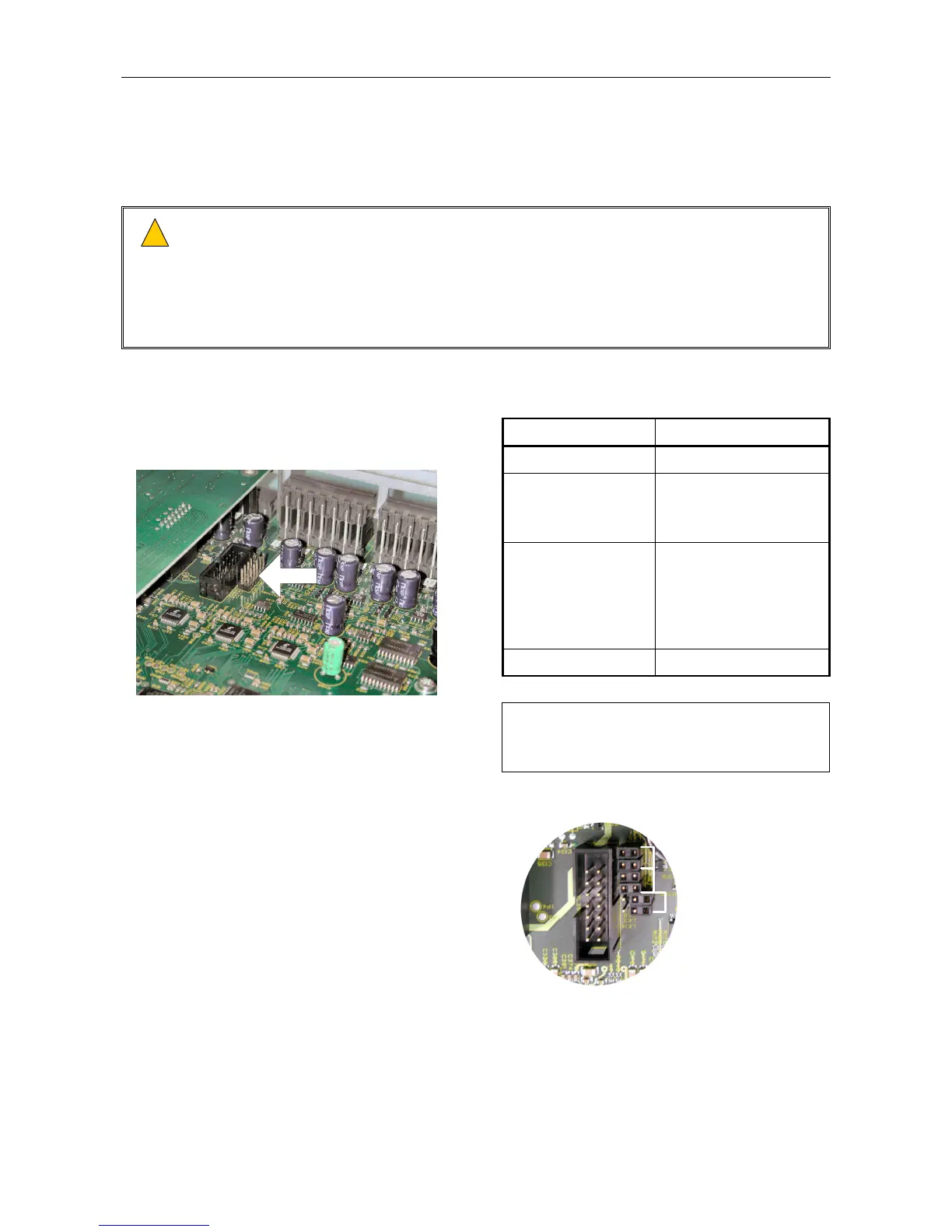
The link position is shown in the following
figure.
LINKS
NETWORK CARD
REAR PANEL
ROUTER BOARD
L
Unfit the jumpers as shown in the
following figure, to avoid losing
them.
LINK SETTING EXAMPLE
CH3 - NOT FITTED
CH2 - FITTED
CH1 - FITTED
3. Re-fit the lid.