VAR8 and Variants Operation, Commissioning, Fault Finding, and Maintenance Guide
sue: 02 complete, approved
-
Is
Page 93 of 166
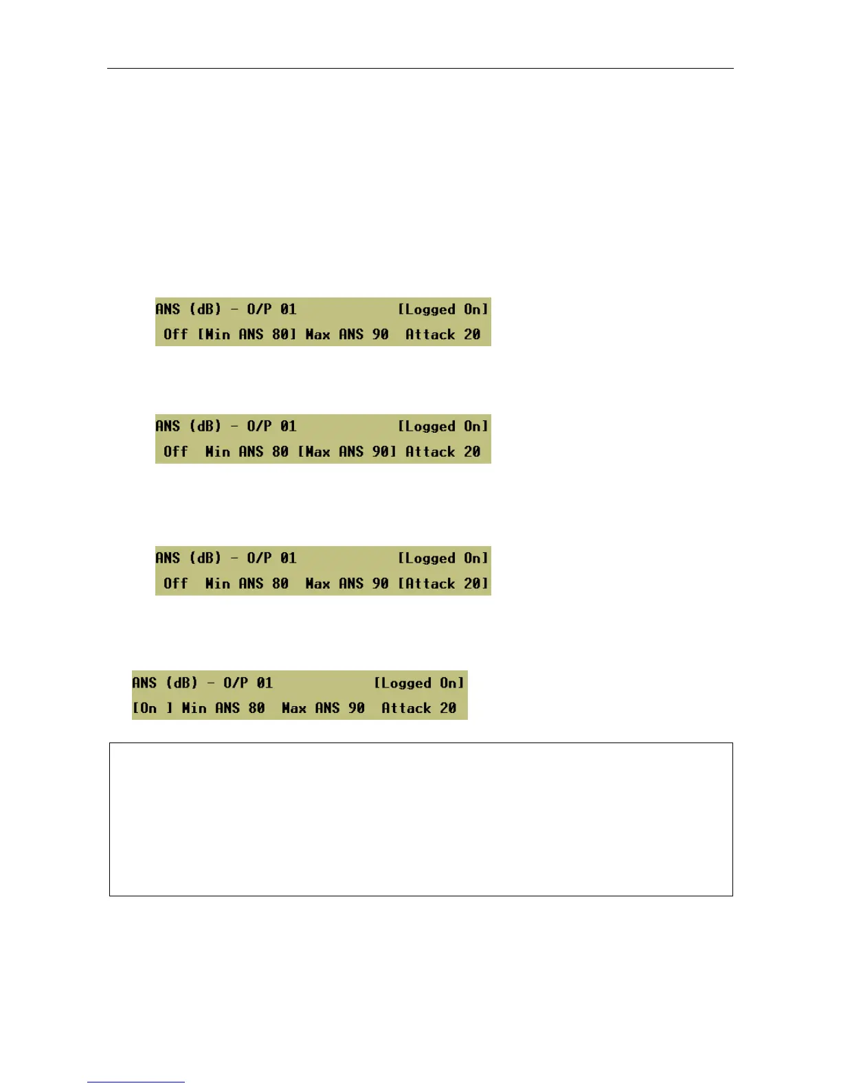
18.2 Output Configuration for ANS Monitoring
To Configure Outputs Controlled by ANS Sensors:
1. For each output, configure the ANS parameters as required, where:
• Min ANS:
This is the minimum threshold value of the ambient noise in the zone (in dBA). This is used to limit
the range over which the gain may be reduced. When the ambient noise reaches or is below this
value, the Router applies the maximum reduction to the output gain. Therefore this has the minimum
gain, and a lower ambient noise will not reduce the broadcast volume further.
• Max ANS:
This is the maximum threshold value of ambient noise in the zone (in dBA). When the ambient noise
reaches or exceeds this value, the Router applies the full configured output gain for the zone.
• Attack:
The Attack Time controls the rate at which the Router can increase the gain when the ambient noise
rises. This is to stop the ANS system from suddenly increasing the broadcast volume in response to
any short-term increases in ambient noise.
The diagram in Figure 9 illustrates the ANS operation.
2. For each output, enable or disable the ANS function as required.
Menu: ConfigurationÆSystemÆRouterÆOutputsÆO/P #<n>ÆANS
L
• Even if the ANS function is enable, the ANS function is only active if the output has been
assigned to an ANS sensor; see Section “18.1 ANS Connection to Remote I/O Unit”,
step 4, page 92.
• The output level (see Section “13 Output/Zone Configuration”, step 3, page 76) should be
adjusted to provide the required maximum volume with the ANS disabled.
• A test function is provided to help adjusting the output level, and to test the ANS sensor
itself. Refer to Section “25.3 Viewing the Current Ambient Noise Sensor Readings” for
further details.