VAR8 and Variants Operation, Commissioning, Fault Finding, and Maintenance Guide
sue: 02 complete, approved
-
Is
Page 122 of 166
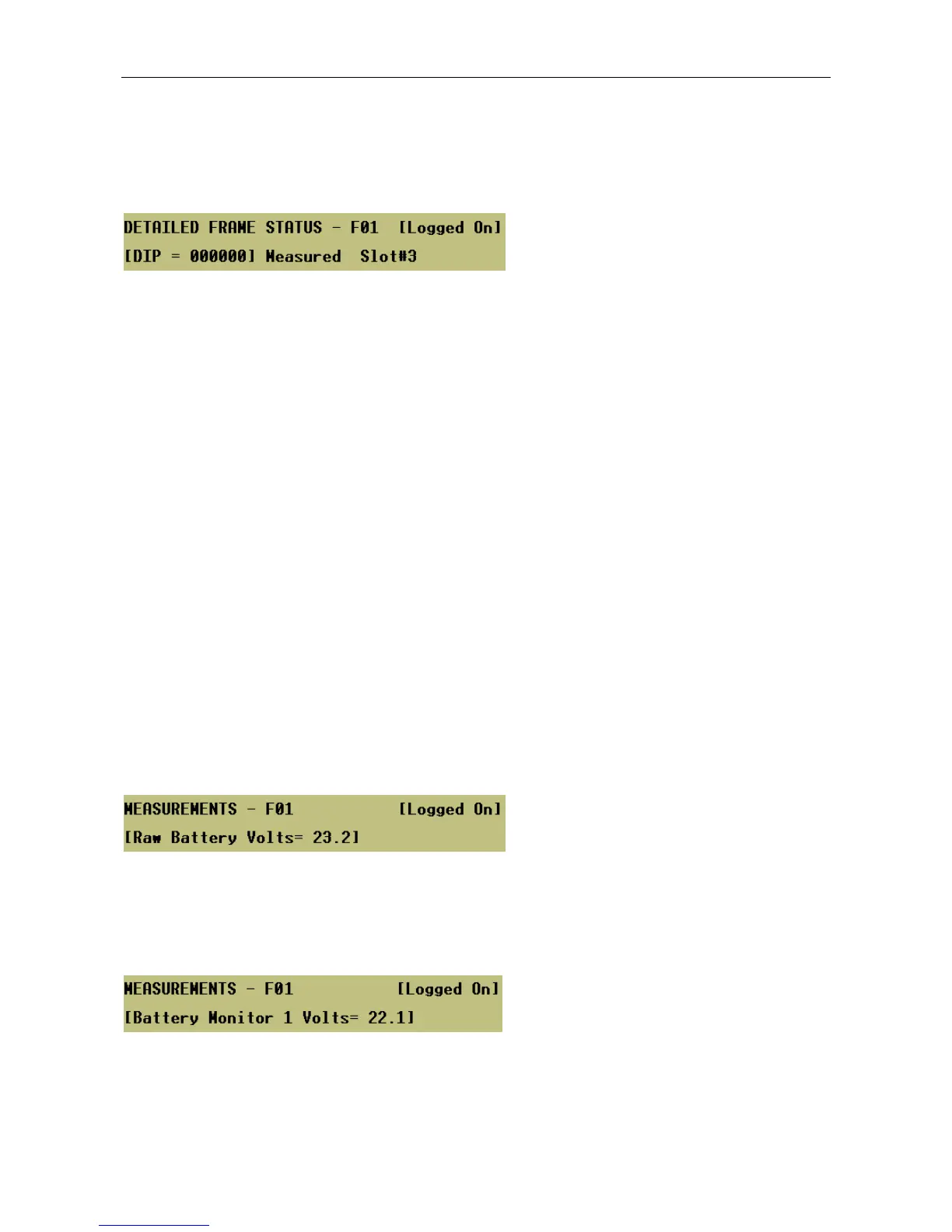
25.6.3 Dip Switch Settings
The settings of the amplifier DIP switches 1 to 6 can be displayed via the following menu.
Menu: TestÆStatusÆFrame#<nn>
DIP = SW6 SW5 SW4 SW3 SW2 SW1
Where:
0 = Switch OFF, 1 = Switch ON
SW1: deep discharge disconnect enable
0 = Automatically switch off the amplifier mainframe if the standby battery supply voltage drops
below 21V.
SW2: mains fault reporting enable
0 = The mainframe is being supplied from batteries only (no AC mains).
SW3: battery fault reporting enable
0 = The mainframe is being supplied from AC mains only (no batteries).
SW4: AUX supply fault reporting enable
1 = Full compliance with BS5839:Part 8:1998 and BS EN60849:1998.
SW5: mainframe CPU faults latching
0 = Mainframe CPU faults not latched by the front panel LED.
SW6: not used
25.6.4 Raw Battery Voltage
The raw battery voltage presented to the selected frame can be displayed via the following menu.
Menu: TestÆStatusÆFrame#<nn>ÆMeasuredÆBAT
25.6.5 Battery Voltage
The monitored battery voltage can be displayed via the following menu.
Menu: TestÆStatusÆFrame#<nn>ÆMeasuredÆB1