VAR8 and Variants Operation, Commissioning, Fault Finding, and Maintenance Guide
sue: 02 complete, approved
-
Is
Page 20 of 166
6. Set the mapping of amplifier slot against outputs so that alarms from the amplifiers are reported to the
corresponding outputs.
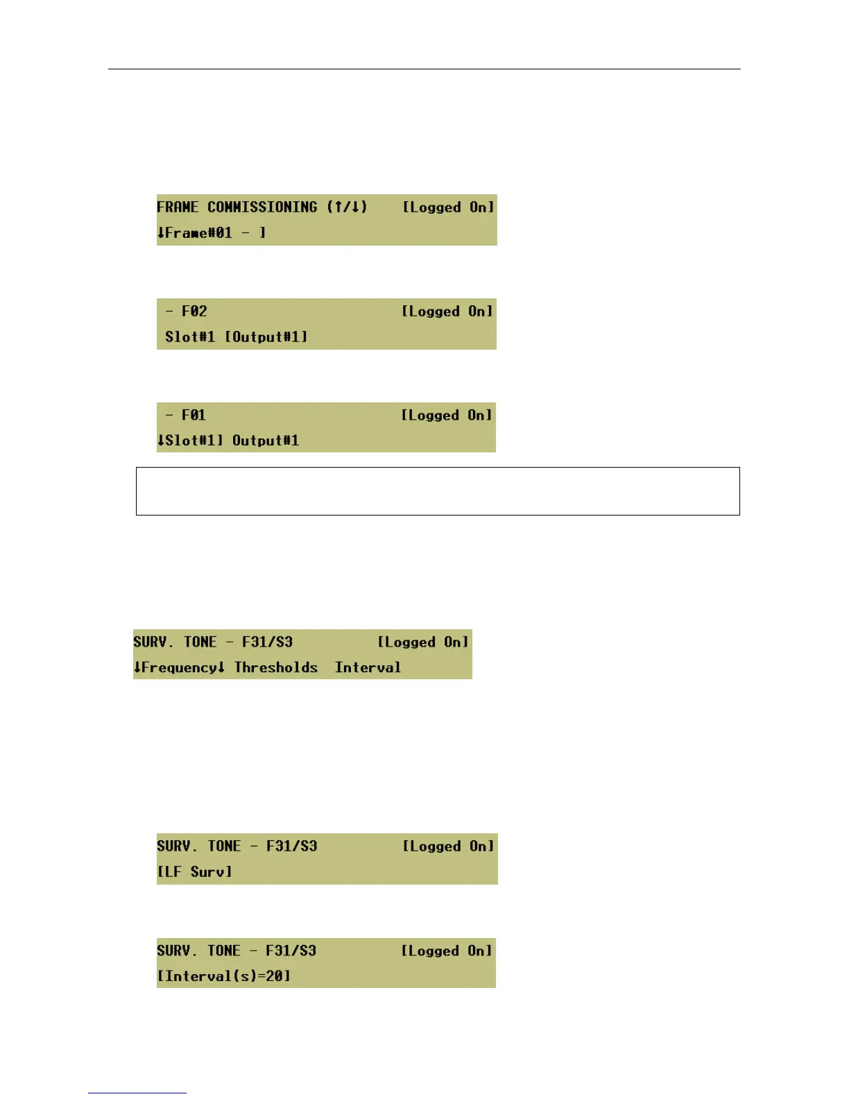
a. First select the amplifier frame from the frame list.
Menu: ConfigurationÆFramesÆFrame#<nn>
b. Select the Router output.
Menu: ConfigurationÆFramesÆFrame#<nn>ÆO/P Map
c. Select the slot to which the Router output is connected.
Menu: ConfigurationÆFramesÆFrame#<nn>ÆO/P Map
L
This configuration must match the amplifier mainframe hardware settings.
7. Set-up the AC surveillance functions for each amplifier slot configured in step 6.
The amplifier’s internal audio path surveillance can be performed by a Surveillance Interface Card.
The Surveillance Interface Card monitors the surveillance tone generated at the Router output, see
Section “13 Output/Zone Configuration” (page 76, step 5).
Menu: ConfigurationÆFrameÆFrame#<nn>ÆSlot#<n>ÆAC Level
a. Select the surveillance tone frequency defined by the Surveillance Interface Card installed:
• None: NSINT Non-Surveyed Interface Card
• LF (Low Frequency): LSDDC Dual DC Line Surveillance Interface Card with Loop Return Option,
SSINT Standby Interface Card; or LSDIC Line Sensing Direct Current Interface Card.
• HF (High Frequency): LSDIC Line Sensing Direct Current Interface Card when it is used in
customised high frequency applications. Please refer to Application Solutions for further details.
Menu: ConfigurationÆFramesÆFrame#<nn>ÆSlot#<n>ÆAC LevelÆFrequency
b. Set the maximum interval between surveillance tones (for pulsed operation) as required.
Menu: ConfigurationÆFramesÆFrame#<nn>ÆSlot#<n>ÆAC LevelÆInterval
If pulses are not received within this interval a fault will be reported.