Page 94 2000-1252-01 Released Rev. C
VersaPort 2200 Technical Manual
Chapter 4: Service
CAP6 – Align Pod-In-Place Switch
a
CAP6 – Align Pod-In-Place Switch
Step 1 Pre-Service
_____1. Raise the port plate to provide easier access to the port door.
_____a. At the Main Menu, select F1 (Auto).
_____b. From the Manual Menu, select F1 (Stage).
Before performing service on VersaPort, service personnel should obtain from the Host
Tool owner, permission to remove the VersaPort from the Host Tool or to work on the
VersaPort at the tool. It is NEVER implied that if the Host Tool owner grants such
permission, a lockout/tagout procedure has already been performed on the Host Tool.
The operator performing the service MUST confirm that Lockout/Tagout of the host tool
has been performed before beginning the service.
_____1. Verify the VersaPort is under lockout/tagout conditions. This procedure may be
performed while mounted on the host tool, or after it has been removed.
_____2. Remove the Minienvironment shields.
CAUTION
THE MINIENVIRONMENT CAN BE EASILY DAMAGED BY
MIS-HANDLING. USE CAUTION WHEN REMOVING AND
REPLACING THE MINIENVIRONMENT.
_____a. Remove the minienvironment shields. Remove the outer two shields by
removing the four screws at the top (two each side). Grasp the
minienvironment shields at the sides and slide away from the VersaPort.
Lift them slightly and rack gently front to rear if there is resistance when
removing.
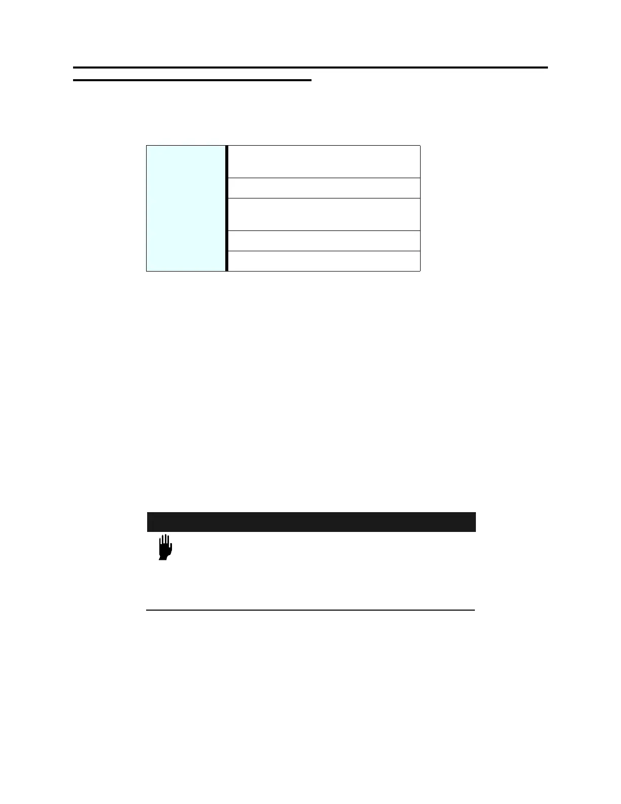
Tools/Required
Equipment
Tool, Pod-in-place sensor adjustment
(Asyst PN 1000-0211-01
Screwdriver, Phillips, No. 1 and 2
Scale or measuring device graduated in
thousandths on an inch
+24VDC power supply
Test SMIF Pod
 Loading...