Released Rev. C 2000-1252-01 Page 67
VersaPort 2200 Technical Manual
Chapter 4: Service
CAP1 – Align Laser Detector System
a
_____6. At the laser diode, use a 5/64 Allen wrench to loosen the screw securing the
laser clamping bracket.
_____7. Gently grip the rear portion of the laser diode body. Insert the paper into the
laser beam path in front of the cassette slot and wafer sensor apertures and
rotate the laser diode in the clamping bracket until beam is parallel to the
wafer slot.
_____8. With the beam correctly orientated, secure laser by tightening the clamping
bracket Allen screw. Verify that the parting line on the laser diode is visible at
the clamping bracket.
Adjust Wafer Sensor Beam
WARNING
LASER HAZARD
LASER RADIATION PRESENT WHEN POWER APPLIED AND
INTERLOCK DEFEATED. AVOID DIRECT EYE EXPOSURE.
_____1. Using ISIM software, at the PC (if not already done):
_____a. From the MANUAL Menu select F4 (DAC).
_____b. From the DAC Menu, use the arrow key to select Sensor Alignment.
_____c. From the SENSOR ALIGNMENT Menu, use the arrow key to select Wafer
Sensor.
_____2. Wait for the software message from the VersaPort. The message should read:
Sensor calibration in progress: WAFER
Adjust sensor by turning the hex screw until threshold is <30
Press F4 key to stop calibration
DAC #0 threshold = xx
(where xx is the DAC threshold value of the sensor and it could range
anywhere from 0 to 255. Where 0 is the theoretical best signal and 255 is no
signal).
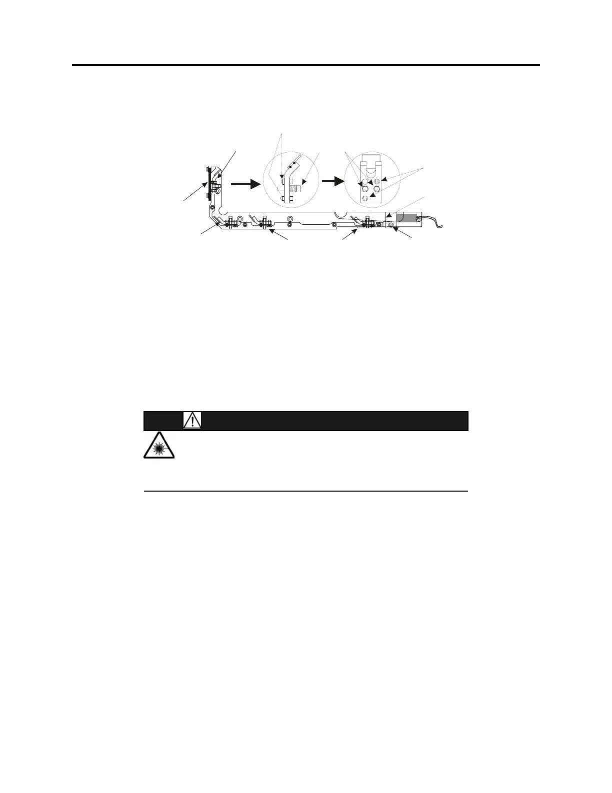
F
IGURE 21 Laser Bracket Assembly
Adjustment
Screws (2)
Position laser flush
with edge of bracke
Beam splitter
Clamping Bracket
Corner Mirror
Wafer Protrusion
Mirror
Screws w/springs (2)
Adjustment Screws (2)
Slide
Bracket
 Loading...