Page 18 2000-1252-01 Released Rev. C
VersaPort 2200 Technical Manual
Chapter 2: Theory of Operation
a
The VersaPort is mounted to the Process Tool with a customer-supplied standard
mounting platform or with an Asyst-supplied SEMI standard (E 63) BOLTS interface
frame.
F
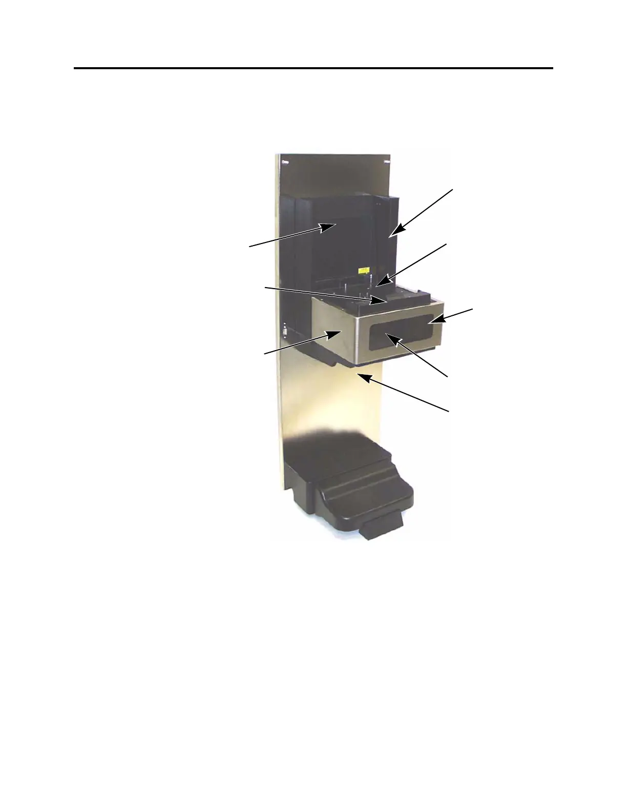
IGURE 4 VersaPort components (with BOLTS interface)
Smart-Probe embedded
in port plate
Cassette shuttle and
motor in base
Fan motor in base
Port plate assembly
Vertical drive column
(lead screw) with
motor in base
Connector panel
behind
minienvironment
shield (routed below
base on BOLTS
model)
Rear shroud
 Loading...