Released Rev. C 2000-1252-01 Page 23
VersaPort 2200 Technical Manual
Chapter 2: Theory of Operation
VersaPort Components
a
Interlocks, Parallel, I/O
The parallel I/O external connector provides for seven optically isolated inputs and seven
outputs. These I/Os are for Host interlock data going to or coming from the Process Tool.
See Table 3, “Parallel Communications Interface - Asyst Compatible,” on page 30 for a
list of inputs and outputs. This connector may be used for parallel communications with
the Process Tool under certain limited circumstances.
Digital I/O
The digital I/O block communicates with the CPU via the computer data bus. Digital I/O
latched output lines are for control and annunciation by LED indicators. Inputs for
interlocks/parallel communications, limit switches, and sensors are read into the CPU via
the input lines of the digital I/O.
Watchdog Timer.
The watchdog timer resets the CPU on powerup. If the watchdog timer
fails to receive a pulse from the CPU via the digital I/O every 600 msec., the CPU will be
reset. The watchdog timer will halt the CPU if the CPU voltage falls below 4.5 vdc. This
ensures that the CPU is properly executing instructions and no associated failure has
occurred.
Interrupt Controller
The interrupt controller accepts inputs from the quad-serial UART, elevator servo-motor
controller, digital I/O, and the horizontal view and slot sensors to provide interrupt data to
the CPU.
Sensors
The VersaPort uses optical sensors; either break-the-beam type or beam intensity
threshold type.
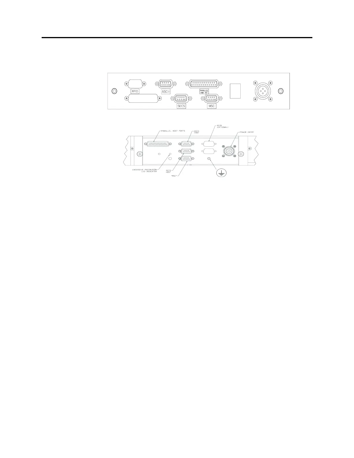
FIGURE 6 VersaPort Connector Panel
VersaPort BOLTS connector panel
VersaPort Standard mount connector panel
 Loading...