Page 78 2000-1252-01 Released Rev. C
VersaPort 2200 Technical Manual
Chapter 4: Service
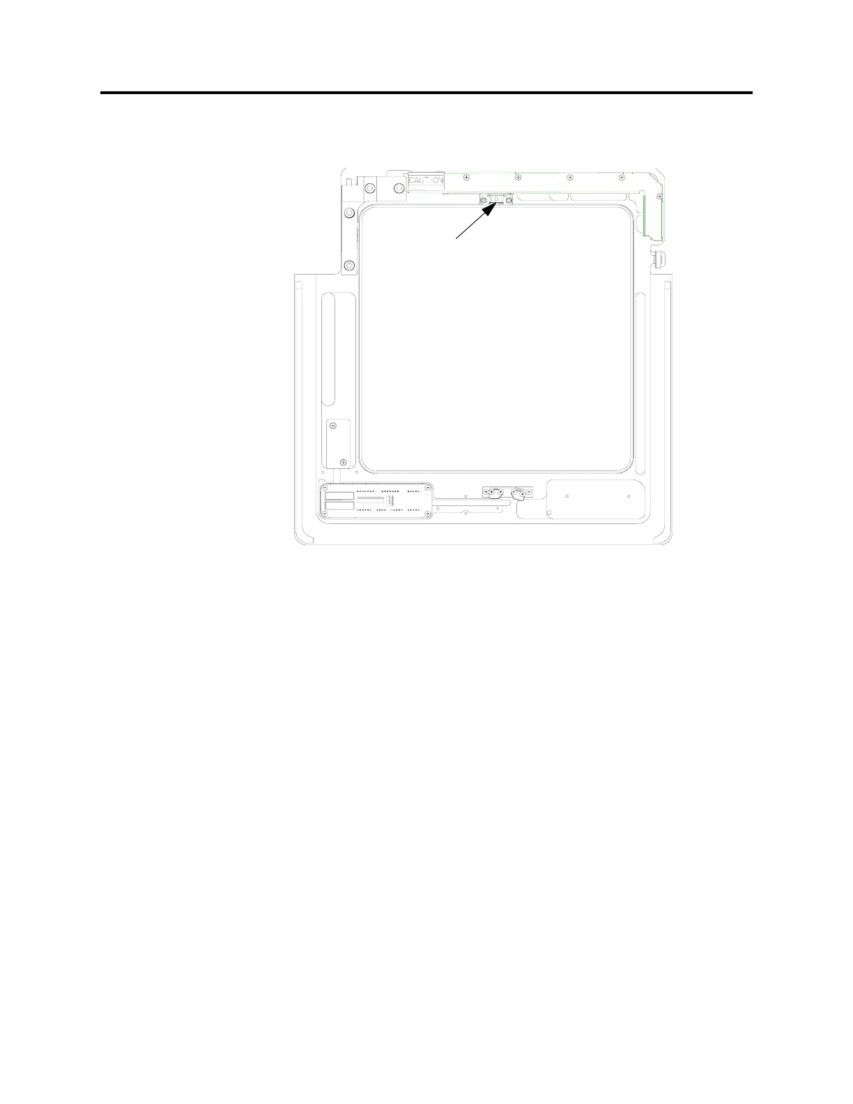
CAP2 – Align Excessive Wafer Protrusion Sensor, Vertical View
a
_____4. Place a wafer by hand directly under the excessive protrusion sensor (see
Figure 24).
_____5. Command the VersaPort to return Home, select F2 (Home) from the AUTO
Menu.
The wafer should block the receiver sensor and the VersaPort should halt. An
Excessive Wafer Out error message should be displayed on the PC.
_____6. Reset the error. Select F10 (MAIN Menu), then F2 (MANUAL) and F8 to
(CLEAR ERROR)
_____7. If the VersaPort detected the wafer, no alignment is necessary. Select F10
(MAIN Menu), then F1 (AUTO) and F2 (HOME) to return the VersaPort to
home. Disconnect the PC.
If the VersaPort did not halt, proceed with the Service section below.
Service
The potentiometer is properly adjusted when the LED on the connector panel blinks
approximately two times per second at the stage position.
F
IGURE 24 Wafer Excessive Protrusion Sensor
Wafer Excessive
Protrusion Sensor
 Loading...