Page 68 2000-1252-01 Released Rev. C
VersaPort 2200 Technical Manual
Chapter 4: Service
CAP1 – Align Laser Detector System
a
WARNING
LASER HAZARD
LASER ADJUSTMENT SCREWS ARE LOCATED CLOSE TO
CRITICAL MIRRORS AND BEAM SPLITTERS. USE CAUTION. DO
NOT SCRATCH OR MIS-ALIGN MIRRORS OR BEAM SPLITTERS.
The DAC threshold value (xx) needs to be as small as possible. If the
displayed value is less than or equal to 30, proceed to the Slot Sensor Beam
Adjustment.
If the displayed DAC threshold value is greater than 30, align the angle of the
beam splitter which directs the laser beam onto the wafer-position sensor
aperture.
_____3. Use a 0.050 inch Allen wrench to adjust the beam by slightly turning the
adjustment screws- not the screws with spring (See Figure 21 for correct
screw). Visually verify that the laser beam is hitting directly on the center of the
wafer sensor aperture.
NOTE . . .
IF THE ADJUSTMENT SCREWS ARE TIGHT AND THE BEAM DOES NOT MOVE,
LOOSEN THE TWO SCREWS WITH SPRINGS ATTACHED APPROXIMATELY
ONE-QUARTER TURN.
_____4. Adjust the beam until the PC displays a threshold value less than or equal to
30.
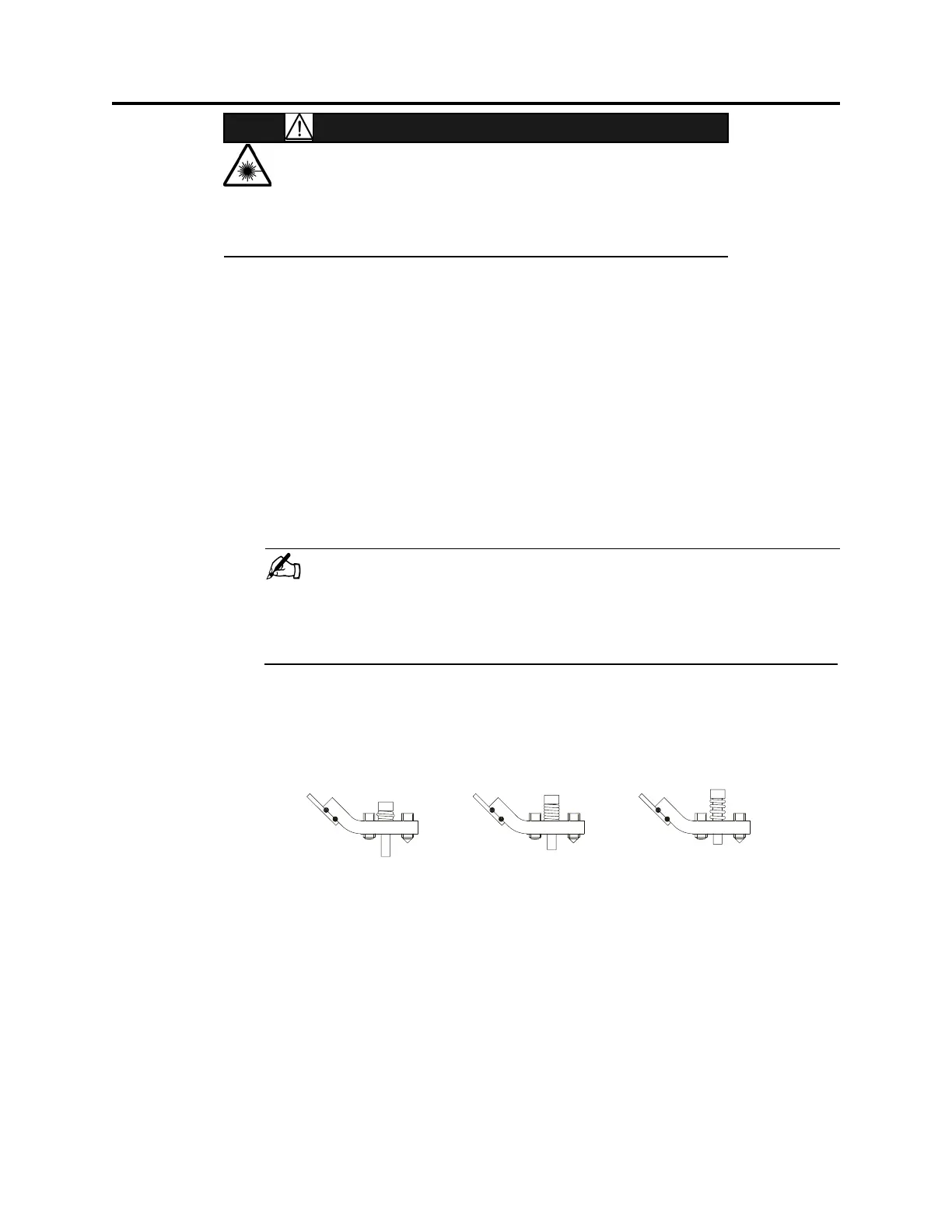
_____5. Tighten the bottom screw with spring until the spring coils touch, as shown in
the center image of Figure 22. Do not over-tighten screw.
_____6. Check the DAC value again. If it is greater than 30, readjust the beam position
using the adjustment screws.
F
IGURE 22 Spring Tension
pring coils crushed
and bulging.
Screw too tight.
Spring coils touching.
Screw snug.
Spring coils open.
Screw too loose.
Wron
Wron
Correct
 Loading...