Released Rev. C 2000-1252-01 Page 25
VersaPort 2200 Technical Manual
Chapter 2: Theory of Operation
VersaPort Components
a
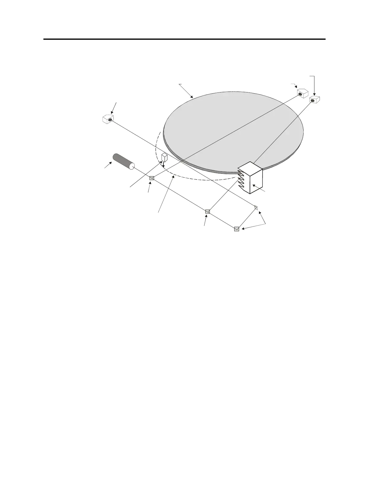
The laser diode, beam splitters, and mirrors are mounted on a laser bracket assembly
that is installed to the bottom of the port plate assembly.
• Wafer Present Sensor, Horizontal View
The laser beam is first directed to a precision beam splitter that reflects a portion
and transmits a portion of the beam. The reflected beam travels across the mid
point of the port opening. On the opposite side of the port door opening, the beam
is directed through an aperture and strikes the wafer sensor. This sensor is used
to furnish positional information about individual wafers. The information is stored
into memory as internal data collected for cassette wafer mapping. The mapping
information is available for use by the Host system to direct the pick and place arm
to accurately retrieve wafers from the VersaPort. This sensor is also used to
determine cross-slotted errors.
• Cassette Slot Sensor
The transmitted laser beam from the first beam splitter is directed at a second
beam splitter. This beam splitter evenly splits the light into two beams. The
reflected beam travels at an angle across the port opening. The beam angle is
aligned to pass on one side of the cassette slot opening as the port plate travels
up or down on the elevator. The beam is projected to the other side of the port
door opening and through an aperture to the cassette slot sensor. The slot
information is available for use by the Host system to direct the pick and place arm
to accurately place wafers back into the cassette.
FIGURE 7 Laser Detector System
WAFER
PROTRUSION SENSOR
SILICON WAFER
CASSETTE SLOT SENSOR
WAFER PRESENT SENSOR
PART I AL VIEW OF
CASSETTE SLOTS
BEAMSPLITTER
BEAMSPLITTER
10 mm
FIRST SURFACE
MIRRORS
2
WAFER AT AN
EXCESSIVELY PROTRUDED
POSITION
<1 mW
LASER DIODE
67O NM VISIBLE RED
BREAK-THE-BEAM
INFRARED SENSOR FOR
EXCESSIVE WAFER
PROTRUSION
(Vertical view)
 Loading...