Page 54 2000-1252-01 Released Rev. C
VersaPort 2200 Technical Manual
Chapter 3: Diagnostics and Troubleshooting
Jumper Post Configurations
a
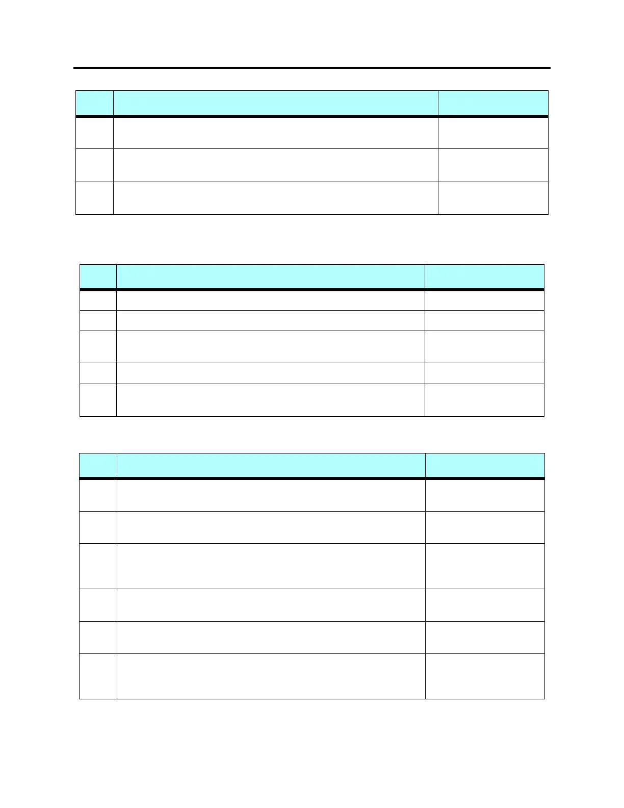
TABLE 9 VersaPort Piggyback Circuit Board Jumper Post
T
ABLE 10 Versaport Control Interface Circuit Board - Single PCB Style
W108 IR Sensor ON/OFF circuit. Connecting 1 to 2 will turn on/off 24V devices.
Connecting 2 to 3 will turn on/off 5V devices.
1 to 2
W109 Internal/External photoelectric sensor input. Connecting 1 to 2 uses remote
sensor. Connecting 2 to 3 uses on board Banner MPC3 amplifier unit.
2 to 3
J1 Remote sensor. Connecting 1 to 2 disables sensor input. If sensor is
connected all three pins are used.
1 to 2
1. Install the terminator for RS485 if VersaPort is the first or last device on the network chain.
Function Jumpers As Shipped
W1 No function Removed
W2 Install only for 256K byte RAM at U11 Removed
W3 Install 1 to 2 for 128K/ 256K byte (+5v) FLASH Memory, otherwise
leave jumper off
Removed
W4 Installed for normal operation. Removed only for troubleshooting Installed
W5 Removed for 600 msec. Watchdog Timer delay. Installed for 150 msec.
Watchdog timer delay
Removed
(Not User Selectable)
Function Jumpers As Shipped
W101 Connects address line A18 to EPOM. If open, 256k bytes are
addressable. When shorted, 512k bytes are addressable.
Removed
W102 Connects address line A17 to SRAM. If open, 128k bytes are
addressable. When shorted, 256K bites are addressable.
Removed
W103 For use with flash proms. Connecting 1 and 2 allows address line A18 to
be used for a 512k byte flash prom. Connecting 2 and 3 allows the flash
to be written to (programmed).
Removed
W104 Watchdog strobe line. Installed for normal operation. Removed only for
troubleshooting
Installed
W105 Watchdog timer delay. Open provides 600 msec. Installed provides 150
msec delay.
Removed
W108 Laser on/off circuit for remote sensor heads. Connecting 1 and 2
provides turn on/off for 24V devices. Connecting 2 and 3 provides turn
on/off for 5V devices.
Installed on pins 1and 2
TABLE 8 VersaPort Control Interface Circuit Board - Dual PCB Style (Continued)
Function Jumpers as Shipped
 Loading...