Page 52 2000-1252-01 Released Rev. C
VersaPort 2200 Technical Manual
Chapter 3: Diagnostics and Troubleshooting
Jumper Post Configurations
a
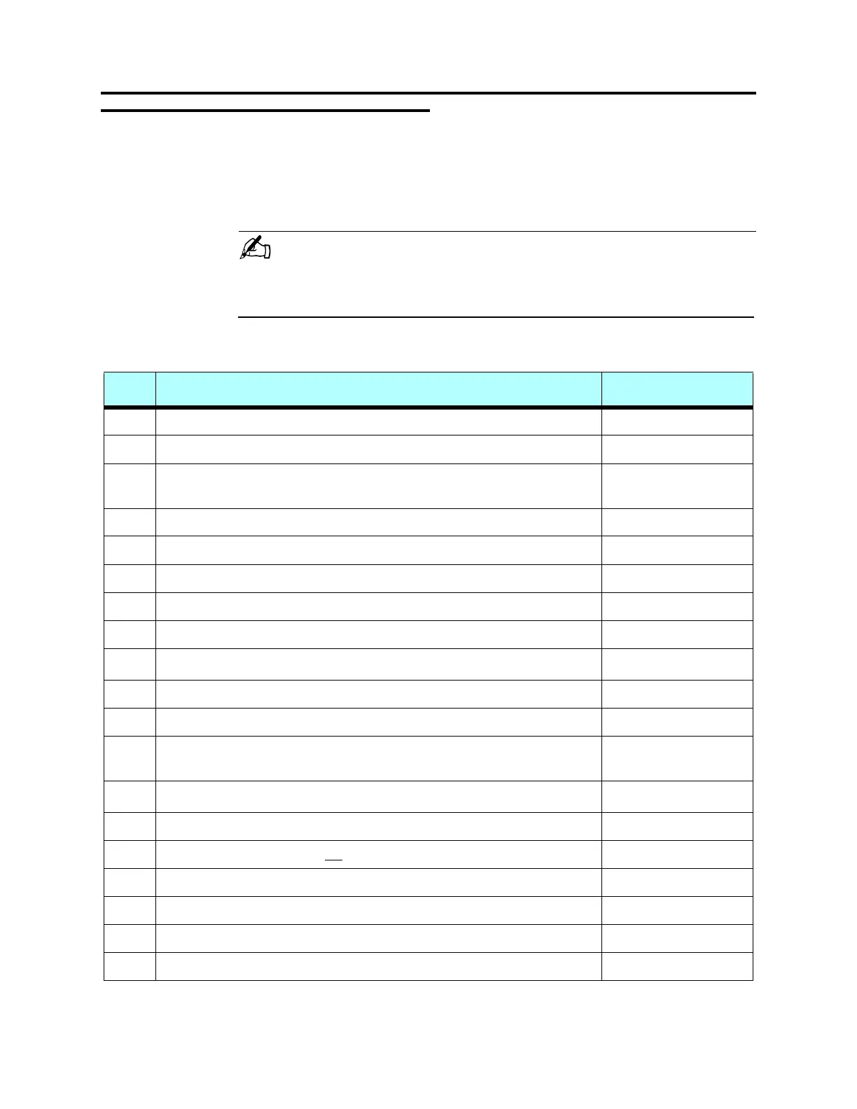
Jumper Post Configurations
Table 8 shows the main circuit board and integrated circuit board jumper post
configurations.
NOTE . . .
FEATURES SELECTED BY JUMPERS FOR RS485 MAY NOT BE AVAILABLE DUE TO
SOFTWARE IMPLEMENTATION.
T
ABLE 8 VersaPort Control Interface Circuit Board - Dual PCB Style
Function Jumpers as Shipped
W1 Ties +24v GND to Chassis GND Removed
W2 Connects DTRC output to RS232 Port C, no jumper = High True Removed
W3 Fan voltage: direct from +24v input (1 to 2), direct from +24v SW, switched
output (2 to 3)
(1 to 2) *Hardwired*
W4 TxD- output: 1 to 2 selects RS232, 2 to 3 selects RS485 1 to 2
W5 When installed, connects TxD- output to RxD- input for RS485 half duplex Removed
W6 CTSD input: 1 to 2 allows RS232, 2 to 3 allows RS485 1 to 2
W7 RxD input: 1 to 2 allows RS232, 2 to 3 allows RS485 1 to 2
W8 RxD- input: 1 to 2 selects RS232, 2 to 3 selects RS485 1 to 2
W9 When installed, provides RxD- and RxD+ terminator for RS485
1
Removed
W10 When installed, connects TxD+ to RxD+ input for RS485 half duplex Removed
W11 When installed, allows RS485 TxD+ output Removed
W12 1 to 2 enables RS485 outputs RTSD+ / RTSD- and TxD+ / TxD-, 2 to 3
allows enabling by RTSD output
Removed
W13 When installed, provides RTSD- and RTSD+ RS485 terminator
1
Removed
W14 Installed it provides RTSD+ output to CTSD+ input for RS485 half duplex Removed
W15 Installed only where laser is not
used for Horiz. Wafer Protrude Sensor Removed
W16 RTSD- output: 1 to 2 selects RS232, 2 to 3 selects RS485 1 to 2
W17 CTSD- input: 1 to 2 selects RS485, 2 to 3 selects RS232 2 to 3
W18 Installed it connects RTSD- output to CTSD+ input for RS485 half duplex Removed
W19 When installed, allows RTSD+ output for RS485 Removed
 Loading...