Page 66 2000-1252-01 Released Rev. C
VersaPort 2200 Technical Manual
Chapter 4: Service
CAP1 – Align Laser Detector System
a
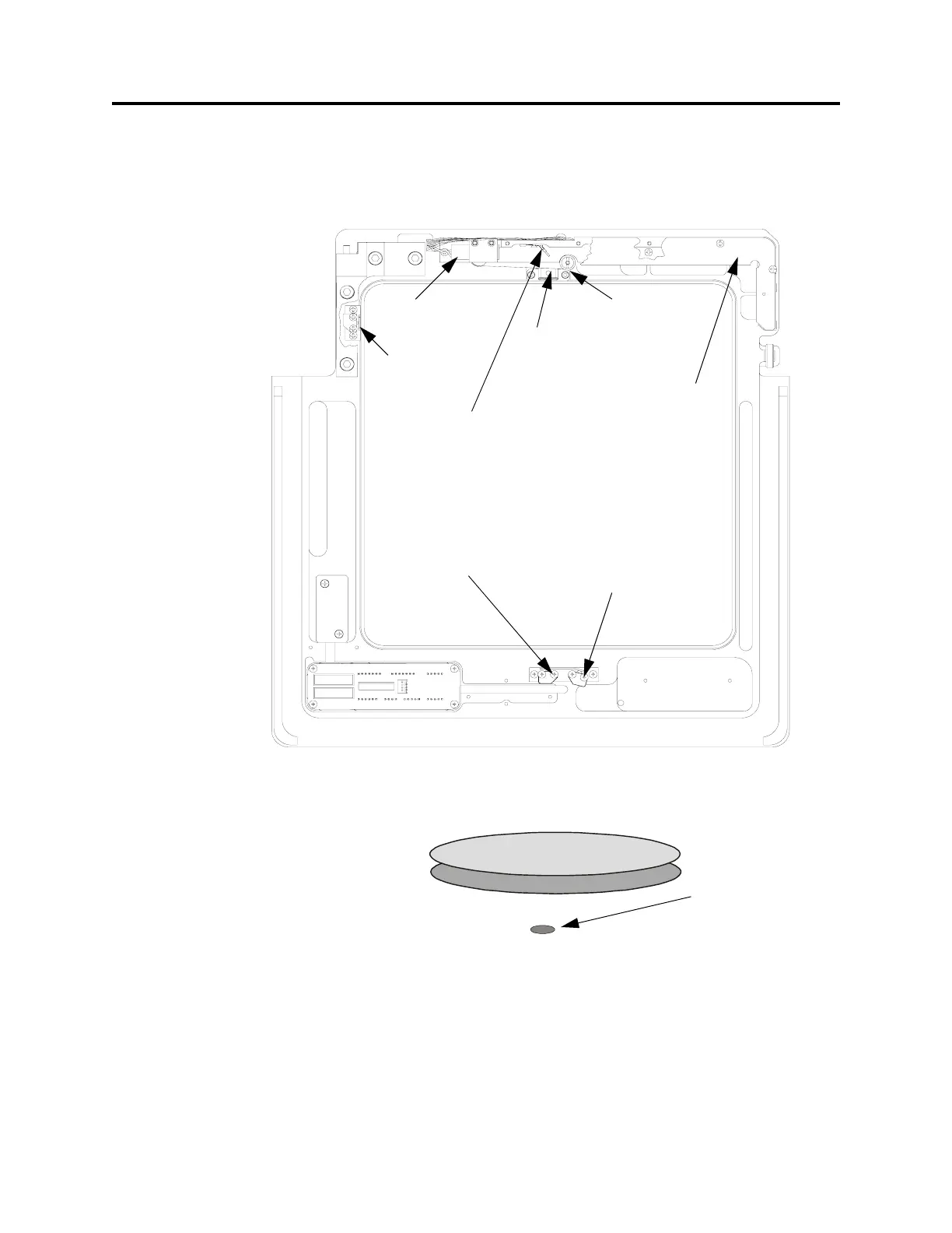
_____4. Insert a white sheet of paper into the laser beam path in front of the cassette
slot and wafer sensor apertures (See Figure 19). Observe the beam
orientation. The beam emitted from the laser is oval. The elongated part of the
beam must be parallel with the orientation of the wafers (see Figure 20).
_____5. If the laser beam is not parallel to the wafers, continue with the next step to
align the beam. If the laser is properly orientated, proceed to Wafer Sensor
Beam Adjustment.
F
IGURE 19 Laser Detector System (bottom view)
F
IGURE 20 Laser Beam Orientation
Laser
Diode
Wafer
Protrusion
Sensor
Mirrors and
Beamsplitters
(inside cover)
Wafer
Excessive
Protrusion
Sensor
Wafer Seater
Mechanism
Laser
Bracket
Cover
Wafer Presence
Sensor
Cassette Slot
Sensor
Beam Oval-shaped
 Loading...