Page 30 2000-1252-01 Released Rev. C
VersaPort 2200 Technical Manual
Chapter 2: Theory of Operation
VersaPort Components
a
NOTE . . .
THE PARALLEL INTERFACE ALLOWS LIMITED FUNCTIONALITY TO THE
V
ERSAPORT. THE SOURCE OF ANY ERRORS ENCOUNTERED IS NOT DISPLAYED
AND ERRORS CAN ONLY BE RESOLVED WITH THE CLEAR ERROR-HOMING CAL
COMMAND. ASYST RECOMMENDS PARALLEL INTERFACE BE USED FOR
INTERLOCK PURPOSES ONLY.
One 25-pin male D-subminiature connection is available. Parallel control is limited to
OPEN and CLOSE commands. The parallel port cannot be used for configuration control.
Configuration modifications must be made through the serial connection. (If the Process
Tool does not have serial capabilities, an external Host PC can be used to set up
configuration data using Asyst ISIM software.)
The inputs and outputs use optical isolation, therefore electrical isolation is maintained
only as long as a separate Host +5 VDC and ground is used to drive the outputs. The
VersaPort internal +5 VDC and Ground can be used, but will not provide electrical
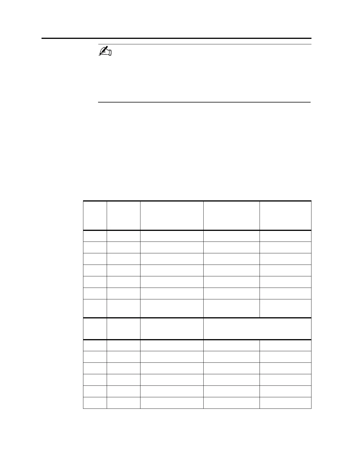
isolation of I/O pins. See Table 3 for the function of each pin.
T
ABLE 3 Parallel Communications Interface - Asyst Compatible
Pin
No.
Type Configuration
ON Current
Requirement
Min. Max.
OFF Current
Requirement
Max.
2 Input ENABLE / DISABLE 3 20 mA 0.40 mA
4 Input OPEN / CLOSE 3 20 mA 0.40 mA
6 Input Not used 3 20 mA 0.40 mA
8 Input READY TO CLOSE 3 20 mA 0.40 mA
10 Input READY TO OPEN 3 20 mA 0.40 mA
12 Input Not used 3 20 mA 0.40 mA
19 Input
CLEAR ERROR /
HOMING CAL
3 20 mA 0.40 mA
Pin
No.
Type Configuration Minimum sinking current capability
5 Output READY TO XFER 8 mA @ 0.4V
7 Output HOME 8 mA @ 0.4V
9 Output POD IN PLACE 8 mA @ 0.4V
11 Output READY 8 mA @ 0.4V
15 Output Not used 8 mA @ 0.4V
16 Output Not used 8 mA @ 0.4V
 Loading...