Released Rev. C 2000-1252-01 Page 79
VersaPort 2200 Technical Manual
Chapter 4: Service
CAP2 – Align Excessive Wafer Protrusion Sensor, Vertical View
a
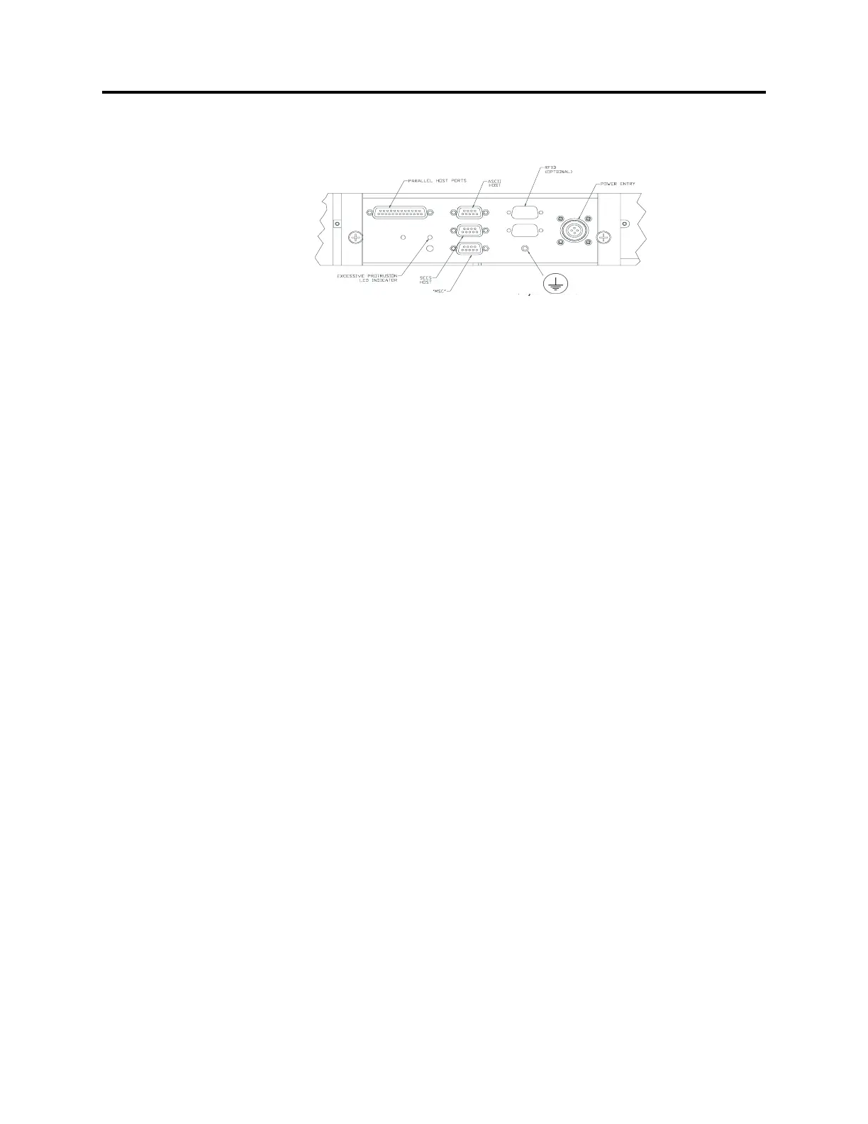
_____1. Check the LED at the connector panel to determine the blink rate.
If the light is blinking more than two times per second, decrease amplifier
sensitivity by turning the potentiometer screw counter-clockwise. Increase
sensitivity by turning screw clockwise
_____2. Adjust the screw until the light blinks approximately two times per second.
_____3. With a Pod on the port door, slide a wafer out of the cassette far enough to
block the excessive protrusion sensor. The LED should be off.
_____4. Repeat Pre-service Steps 3 and 4 to test the sensor. Adjust the potentiometer
screw if necessary.
_____5. If screw adjustment does not correct the problem, troubleshoot the sensor
circuitry or sensor placement (alignment).
_____6. Autocycle the VersaPort to verify operation;
_____a. From the MAIN Menu select F1 (AUTO).
_____b. From the AUTO menu select F9 (AUTOCYCLE).
_____c. If the VersaPort cycles properly, stop the Autocycle function by pressing
F9 again. The VersaPort will complete a cycle and stop at Home.
_____d. Press F10 to return to the MAIN Menu.
_____7. Remove the SMIF-Pod. Raise the VersaPort ten inches to allow cable
connection when remounting to the Process Tool:
_____a. At the Main Menu, select F2 (MANUAL).
_____b. From the Manual menu, select F5 (GOTOPOS).
_____c. At the dialog box, enter “10” on the Target Pos (inch) line. Press Enter
three times to accept Speed and Acceleration values and raise the port
plate ten inches.
Post-Service
_____1. If necessary, return the VersaPort to the Process Tool.
_____2. Reinstall the minienvironment shield.
F
IGURE 25 Excessive Protrusion Sensor
Adjustment Screw